| |
|
|
|
|
|
|
----------------------------------------------------------------------------
Blog Post #124, submitted 6/16/26 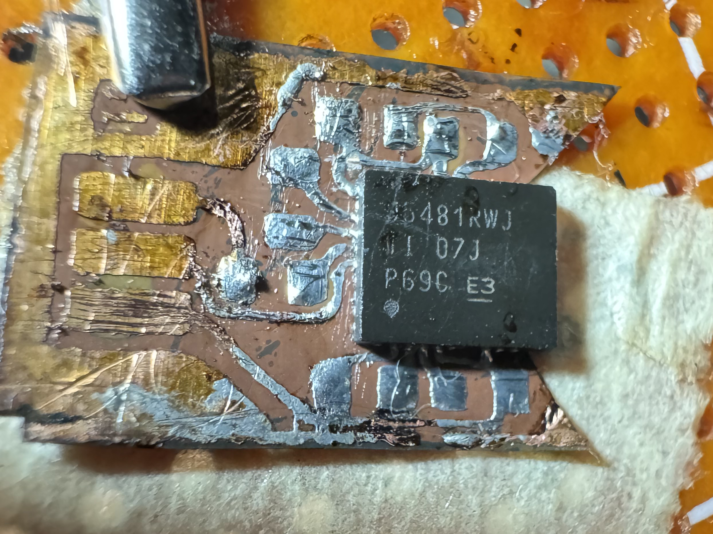
Ok so I had multiple failed attempts to solder the chip on. Despite pretinning the PCB, on both attempts when the solder went molten the chip did not center itself and lock into place as would be expected but instead slid out of position significantly both attempts. After the first attempt I assumed it was the outlet bus/landing pad on the left side of the board that was to blame - it being a larger solder mass than the other solder masses on the other edges of the board - causing the chip to slide its way harder and pulling it off center. However, even after cutting off that part of the board entirely and trying again I still had the chip slide out of place during reflow attempt. It's unclear to me the cause of the issue at this point. I put on AMTECH tacky flux that expired in 2022 onto the pcb and then placed the chip as close as I could to centered and then put it onto a hot plate for cooking food or boiling a coffee pot those AC electric hot cooking plates. I had the heat set to max on there. The first time I had the board on the whole heatup time period and watched it gradually smoke off flux vapors and eventually the solder go molten and then I switched off the hotplate but it didn't matter since the chip slid 5mm off center. The second time I added it after plate was much hotter to avoid so much flux burnoff during the heating up process. I also added some flux while it was molten after which time it slid off center. Perhaps that was my mistake? Not sure. In any case, after the failed second attempt I cleaned everything up really well and chose to hand solder it. This seemed to go better. For this process, since both chip and PCB were fully tinned and no shorts to my knowledge, I proceeded to line up the pins the best I could under max magnification and then while pinching it in place I held my solder iron tip onto a trace near a pin for 5-6 seconds to get the solder very hot and hopefully locally heat the whole trace up to and under the IC's pad. I did this for trace after trace. Then to clean up since it was I guess cold joints at this point I applied flux and drag soldered all around every edge. This cleaned up the appearance and got all flux properly seated on traces since it was drifting a bit in the previous step and looking quite sloppy and bad. I did not want to have flux involved during the initial alignment phase and tacking down phases because once that is on I cannot see well the alignment from the sides since the flux blocks my view. Even without the flux its hard to see the traces and their alignment with the pins of the chip. The chip does not have pins is the problem. It has pads on its underside and little pads on its sidewalls. I have to use the sidewall pads as to verify the pads on my pcb line up with those and any flux in the way prevents me from seeing this clearly even with max magnification on my visor. So anyways yeah, this whole thing was a bit of a disaster but MIGHT have ended ok in the end. For now hand soldering instead of reflow looks like my best bet at least until I can figure out what i'm doing wrong... Note: I'm not sure if the flux expiration matters I haven't looked into what that means for performance. Note: I still have no way to verify all joints are good until I test the whole finished PCB I guess. And my confidence they are all good is a bit low. Sucks that I have to invest even more time to finish the PCB while doubtful it will even have reliable connections at present ugh! Note: I had to remove the trace from the previous post that ran under the chip because during my reflow and cleanup from failed attempts while cleaning some of the solder mask came off and I just wanted to remove that potential short or source of issues as a variable entirely for now. I can always run a bodge wire to reconnect those two points of the board later on. Drop a Comment: Comments: ---------------------------------------------------------------------------- Blog Post #123, submitted 6/7/26 Ok I managed to apply the UV solder mask today and it seems like it worked quite smoothly. I used the tip of a small sewing needle to spread it over the trace and then held the UV light on it for 10 seconds to play it safe. I used transparent UV solder mask so you can still see the trace but its a bit more murky/cloudy when you see it. I used the tip of an exacto knife to put little scratches on the UV solder mask to test its thickness by feel and test its durability a bit to scratching. And ensure it was fully cured. It was very hard and durable and seems to have gone on fairly thin. The question is, is it too thick/proud of the surface for the soldering on of the chip over it? This is the million dollar question. Because if the mask lifts the chip up off the PCB even a tiny bit then the soldering may not reach between pads on the IC and pads on the PCB, failing to bridge the distance. That is my main concern. If I have any issues with that, I will have to reroute this trace to go around everything rather than on the shortest path like it is now. The shortest path leads it under the IC and led me to have to mask it. Extra steps like this are a bit annoying. I kind of wish I just routed it around everything out of the way more. Then I would not need to UV solder mask at all. Perhaps in a future board iteration I will do this improvement but we'll see. For now I made several boards and want to stick to them since it would be more work to remake them all. 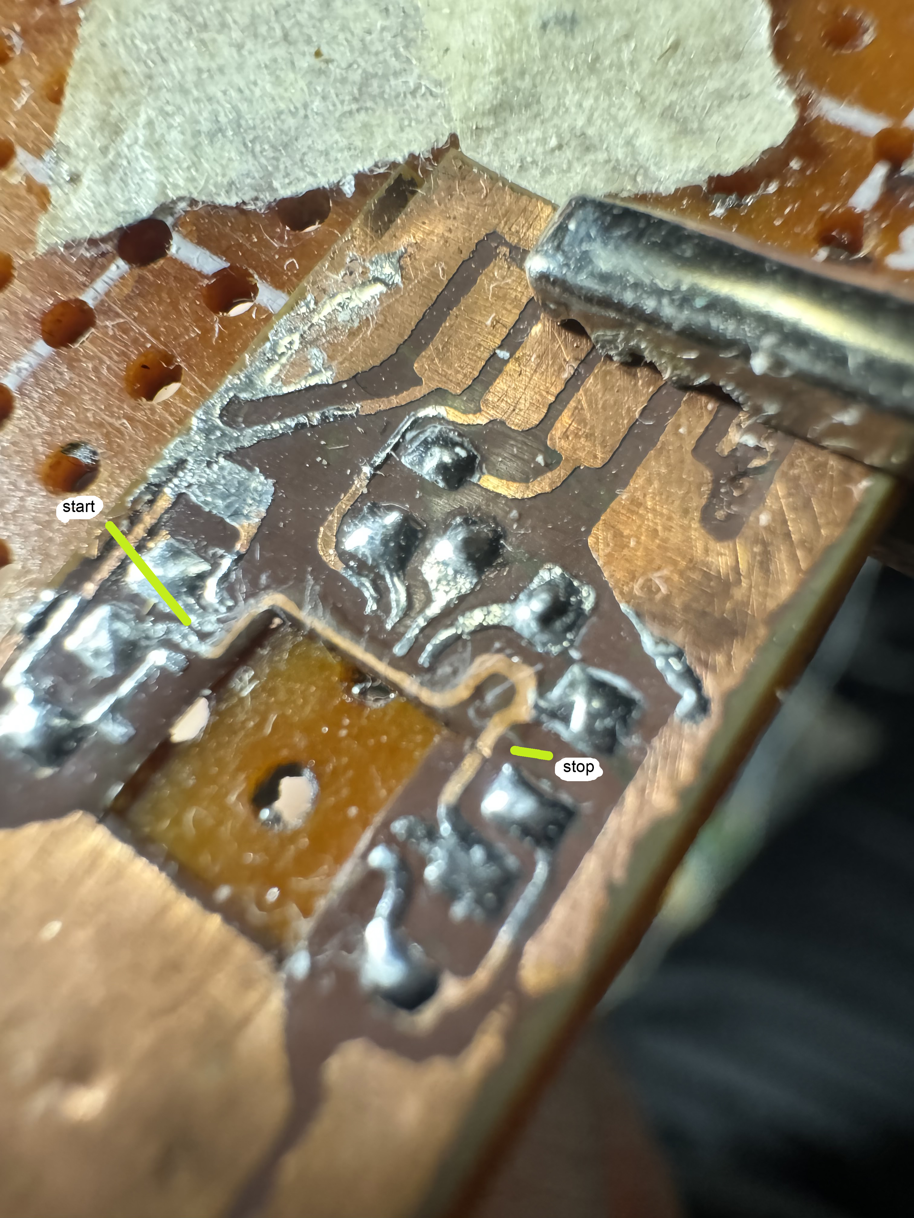
Drop a Comment: Comments: ---------------------------------------------------------------------------- Blog Post #122, submitted 6/3/26 Ok so the Relife RL-UVH902 UV fast cure solder mask order has arrived and so has my order for a Relife UV curing light to cure the solder mask quickly and effectively. So now I just need to solder mask off that little trace that goes under the half bridge IC chip. 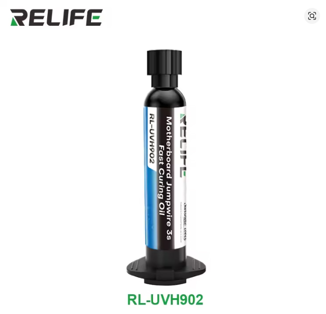

Drop a Comment: Comments: ---------------------------------------------------------------------------- Blog Post #121, submitted 4/28/26 So the plan I have for the heat sinking main conductors that attach to the bottom pads of the IC chip I decided to draw up to explain it. It will be in layers. First you have the chip on the bottom facing bottom side up so the pads are exposed upwards. Then on the first attachment layer I cut out matching shaped copper plates from copper sheeting and solder that down with low temp solder paste and a soldering iron. In theory, this first layer attachment will basically just be extending the pads up past the viewing window of the DIY PCB with cutout viewing window we've made so far so that the DIY PCB we made so far and this first layer of copper plates together act as layer 1. Ideally the copper plates would be slightly proud of the printed PCB in height I think. This first layer copper plates that we are soldering onto the pads of the IC carries the current and the heat sinking to layer 2 without the need for vias. In a multi-layer PCB made industrially, vias would take the heat sinking and current to layer 2 of the board and we are just using solid copper plates instead which should be even better than vias because its solid copper instead of just via holes so more surface area than vias would offer. Now on layer 2 we can create a much larger sheet that extends out past the PCB way off the chip and that portion that extends way off the chip acts as a tab we can solder the V- wire to. It also acts as a tab we can solder our 6 strands of solder wick wire that act as heatsink fins to. Layer 2 also has a plate that brings the V+ to layer 3. For layer 3 we just attach a large sheet of copper which also extends way out past the chip and acts as a tab we can solder our V+ wire to and our heatsink solder wick wires to. 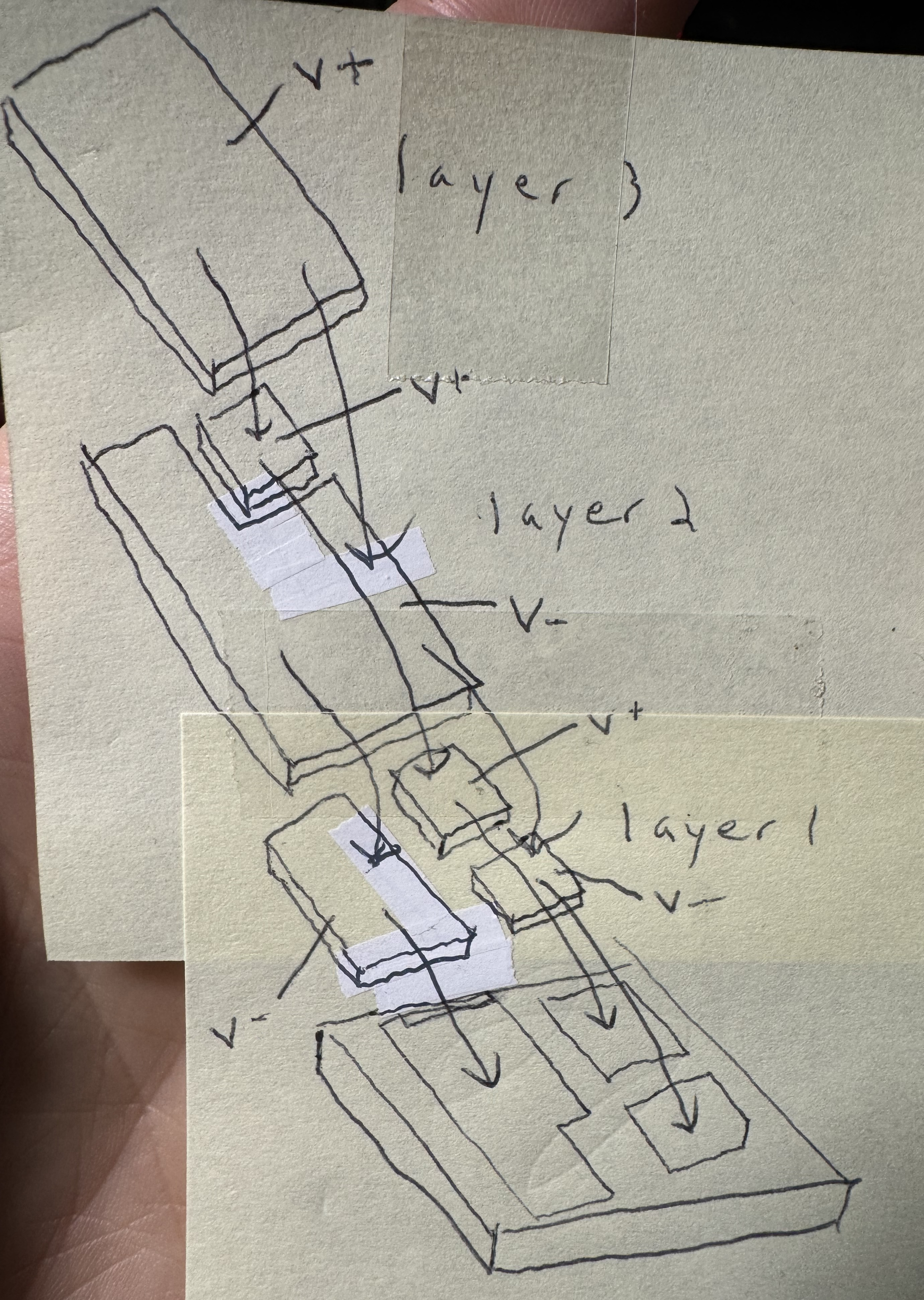
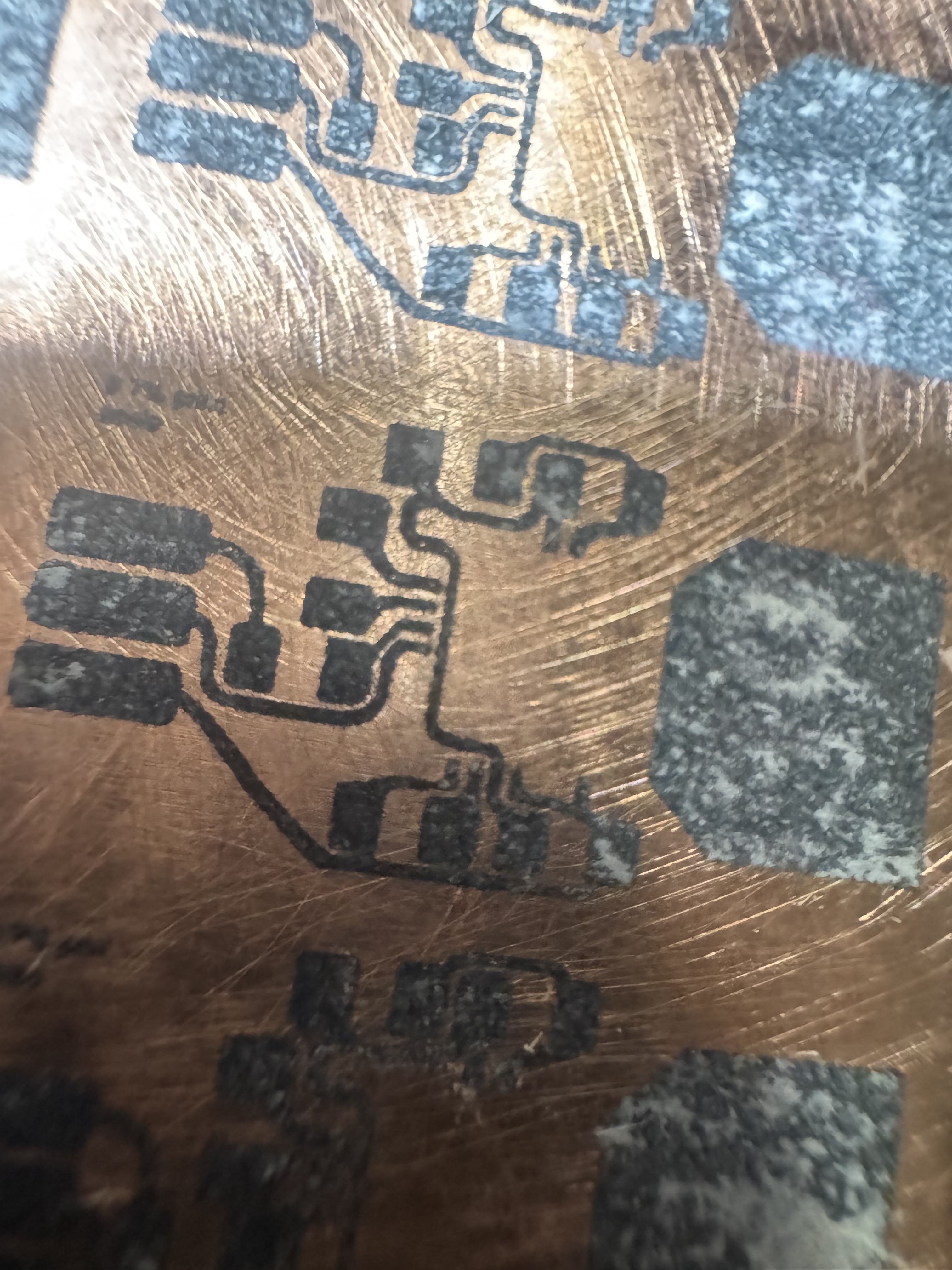
Drop a Comment: Comments: ---------------------------------------------------------------------------- Blog Post #120, submitted 4/4/26 Ok I used the tip of my exacto knife to carefully scoop on low temp solder paste and then carefully drag soldered it over the key areas I wanted pre-tinned. There do not appear to be any short circuits and the amount of solder on each pad and trace seems a decent amount to me. I forgot to wipe it with alcohol wipe but have done so since taking this snapshot. 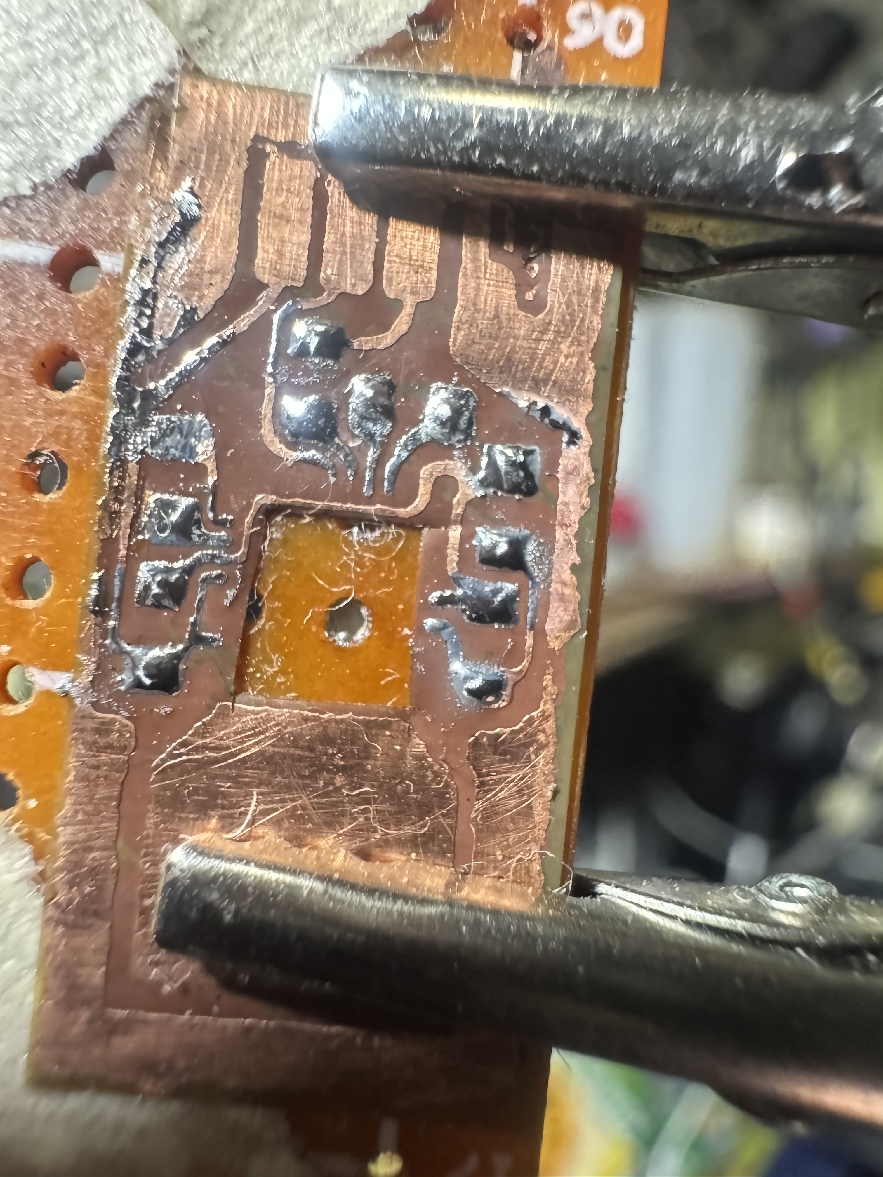
The next step is I have to carefully uv cure solder mask that little trace that runs under the IC chip. It definitely will short a pad to something I think if I don't. I have to apply it very thinly so it doesn't prevent IC chip from seating flat and soldering into place well. Drop a Comment: Comments: ---------------------------------------------------------------------------- Blog Post #119, submitted 3/20/26 So as I fast approach motor controller wiring phase, I figured I would revisit placement again. Upon further reflection I decided hovering midair motor controllers attached to nothing might not work as they'd perhaps be a bit in the way of getting at the motors and just be a bit overwhelming. I'm not positive on this and could revisit the concept but for now I'm thinking of just mounting it side saddle onto the motor again. I decided to place them side by side with inlets on the output shaft end and outlets on the BLDC motor wiring's end. I drew this sketch of the layout and wire flow as a visualization aid. 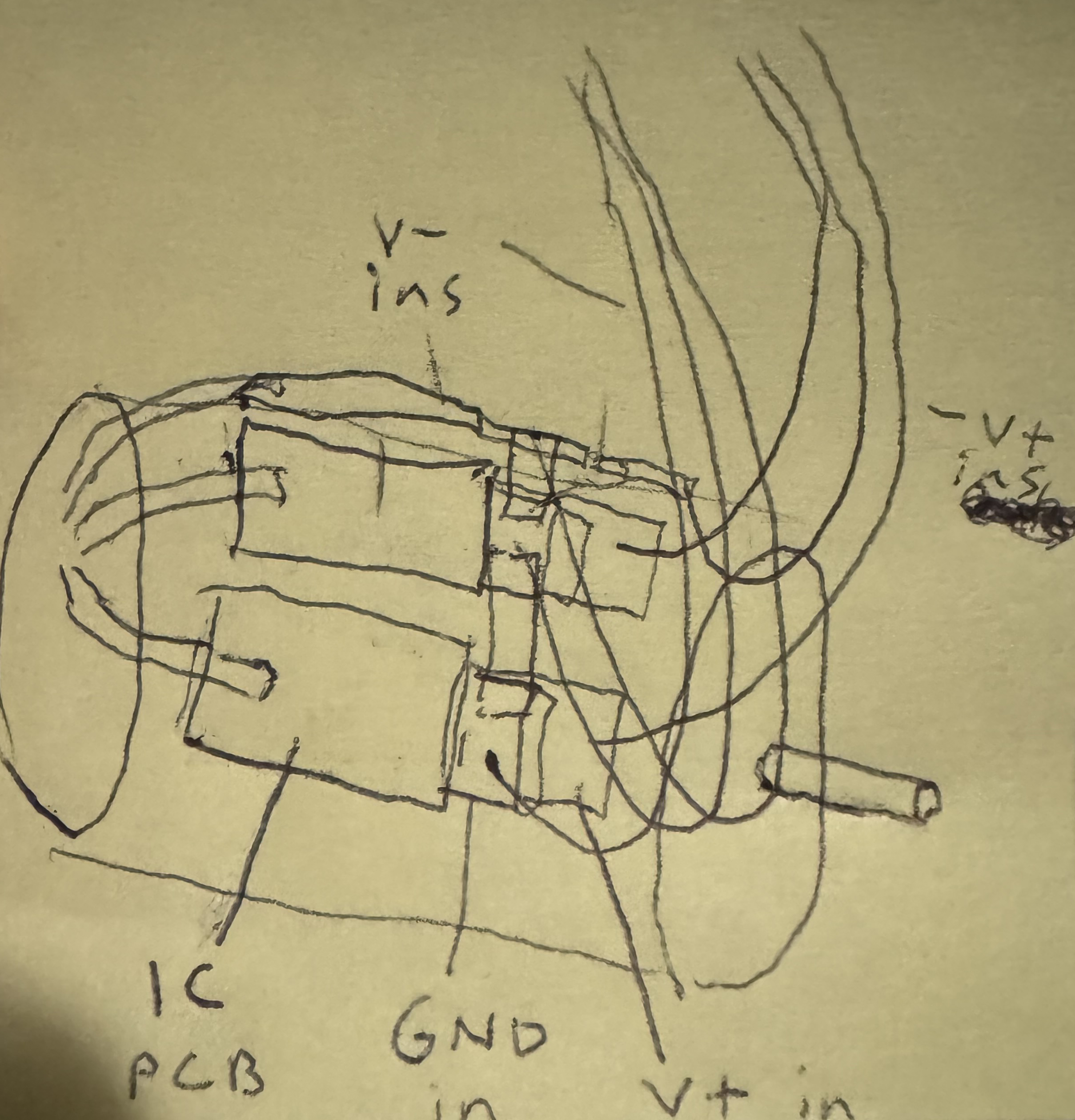
Drop a Comment: Comments: ---------------------------------------------------------------------------- Blog Post #118, submitted 3/19/26 Here's the center cutout now which was the last thing I needed to do before soldering down the chip. This access window will enable me to solder the main power lines to the main pads on the bottom of the chip. The circuitboard is aimed at tying into the various perimeter pins of the chip but this window is for the high power lines on a separate layer below. 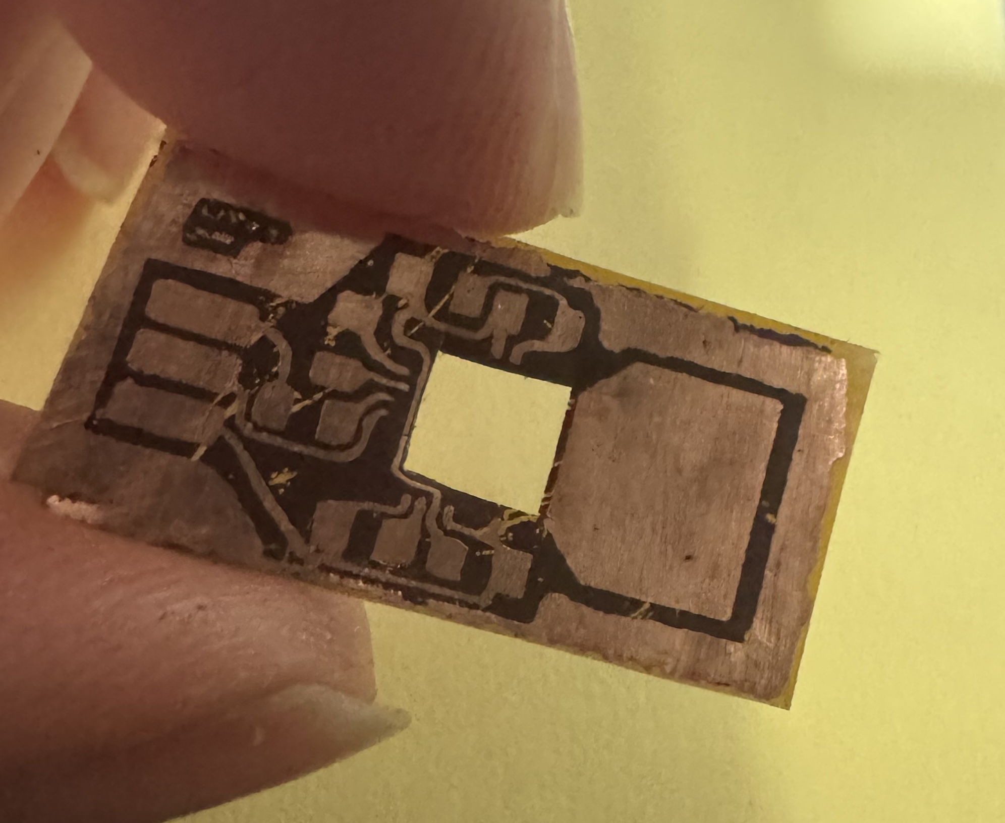
I was able to cut this window out with the highest zoom setting of my magnifier visor (I think like 20x zoom?) and an exacto knife. Quite a challenge but made it happen! Drop a Comment: Comments: ---------------------------------------------------------------------------- Blog Post #117, submitted 3/11/26 I got together my temperature sensor and my hot plate and my glass container and some water and figured out where on the hotplate temp dial I need to be to get the desired water temperature. I then used label paper sticker and marked it off and wrote 118f on it which is the average temperature of that spot on the dial. It has about 15 degrees variance I think up or down. Good enough. Next, I mixed up a batch of water and PCB etchant (Ammonium Persulfate crystals and water mixture) using a postal scale to get the ratios right. I mixed it into the bottom third of a wet ones baby wipes container. It was 0.8oz total. Then I submerged the etchant mix into the warm glass basin of heated water to bring it up to temp. I noticed the etchant wet ones container wanted to tip over so I used scotch tape to tape it off in all 4 directions to the glass container and pull it under water a bit too in order to maximize temperature transfer from the hotter outside water into the etchant container contents to warm it efficiently. I skipped the automated agitator entirely opting to just stir the mix with a hot glue stick manually. 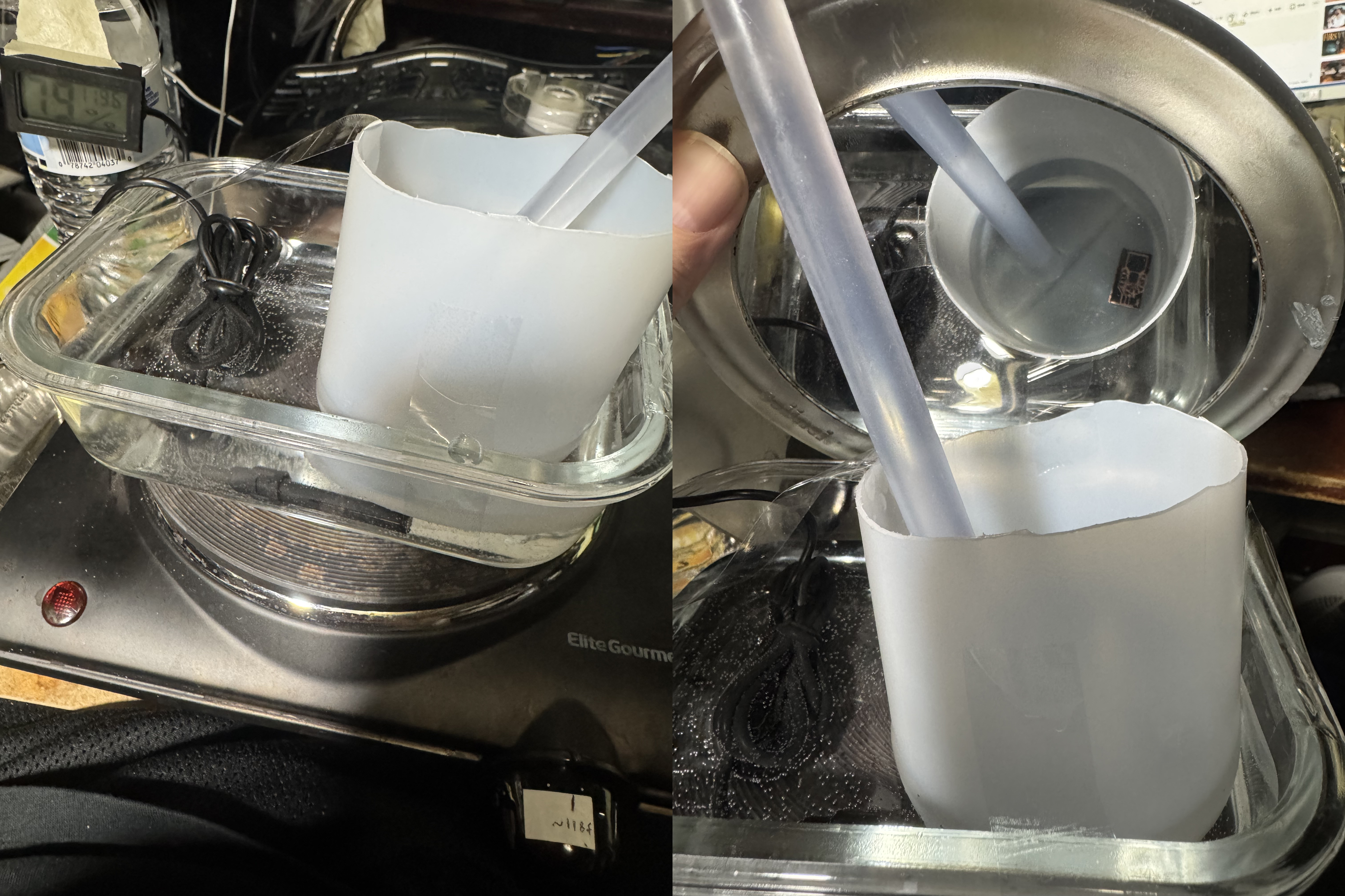
All in all, it did etch within the 5 to 8 minutes range and I think etched even faster when the temperature was closer to 130f - closer to 5 minutes then maybe even 4 minutes I didn't time it. It was lightning fast compared to room temperature etchant which took 2-3 hours to etch a single board. So indeed, the instructions that said room temperature is fine were wrong. All that leads to is undercutting. Anyways, with the stirring and the warm temps my results were significantly improved and almost every board was usable. I produced 8 or 9 in total. Enough to do at least 2 motors and part of a 3rd at least. So plenty for now. I had still a tiny bit of undercutting on the fine traces, but rarely enough to break their continuity. I will make the traces slightly wider in Photoshop for future prints with the expectation that around 15% of the outer edges will be removed so we print wider to compensate and then the result will be the width we wanted in the first place after the undercutting has done its thing. This way the undercutting is worked with and non-detrimental. That's my planned workaround for it. 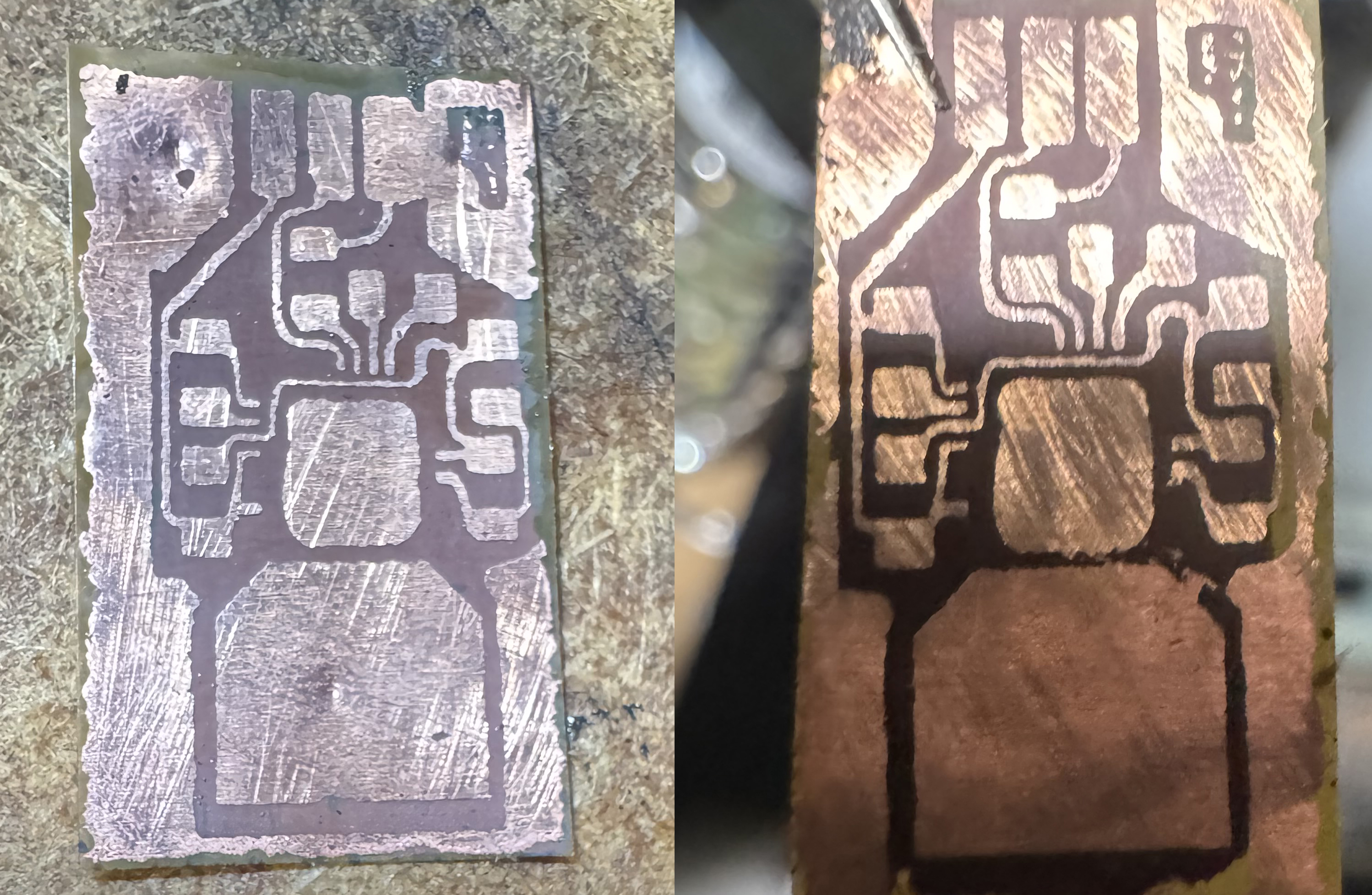
In the rare instance of pinholes randomly in the center of pads or traces or a tiny open circuit on a thin trace, I am confident that a coating of solder over all of those areas will correct that. These little holes and whatnot are microscopically small so very easy to solder bridge as needed. I think for the most part my boards are almost all fully usable as is. I'm sure my methods will improve as I continue to tweak and iterate techniques over time - but the fact that we can already produce working circuits at this extremely fine detail and miniaturization level is already very encouraging. Any improvements from here is just icing on the cake IMO. My next step will be to solder on the half bridge IC chips using the method shown in this video - a method I think looks very impressive and sound and hopefully not too hard to replicate on my end: https://www.youtube.com/shorts/r-HaRjBvWgU Drop a Comment: Comments: ---------------------------------------------------------------------------- Blog Post #116, submitted 3/6/26 Ok so I created what I'm calling the Orchestrator.py, a python code a couple thousand lines long that interfaces with chatgpt, being able to go into my codebase for chatgpt and pull sections of code out and populate my clipboard with that code and ask me to paste it in for chatgpt which I then manually do. Chatgpt outputs commands like list all sections of code in this or that file and if I copy this command, the orchestrator who polls the clipboard goes out and goes into the code file and parses out the code section names and populates the clipboard with it and tells me to paste it in to chatgpt which I then do and then chatgpt is like okay, these 3 code sections we are dealing with for today's project, pull out code section #1 - lists its name and I copy this request into clipboard and orchestrator goes out and pulls that section of code from the codebase, populates it into the clipboard, and tells me to paste this into chatgpt which I manually do. So then chatgpt fully is able to get up to date on the codebase and where we left off. Also backing up a bit, this ALL starts off for a new session in chatgpt with me pasting in a huge context dump about my various projects and the orchestrator.py and the commands it can give the orchestrator.py etc and kind of seeding its context window with what is going on. Then it begins issuing the commands to list sections of code or w/e. Next I have to manually launch the orchestrator.bin file which launches the python code of orchestrator.py which upon opening asks me what code project we are working on this session and gives a window with a list of coding projects we have ongoing. I select from that list the coding project we are doing that session. The orchestrator then takes the coding project I selected and opens up a context txt for that coding project that lists the overall goals of that project, the list of to-dos for it, the most recently completed steps, and where we left off, any constraints, any special notes or rules, any dependencies, any special files or directories the related project files are located in, etc etc. It copies this coding project specific txt extra information into the clipboard and tells me to paste that into chatgpt which I then do manually. So this way chatgpt now has overarching major context dump for all coding projects and then today's coding project specifics for that session. It is now fully equipped to be my coding copilot. The orchestrator saved me just a ton of navigating codebases and files and copy pasting all the time. That is basically its job, to be a bridge for chatgpt and I into the hard drive and the projects. My next plan for making this even more seamless that I have been working on is to make my own diy browser. This browser will then be my interface for chatgpt and will enable my orchestrator.py to tap into what chatgpt is saying to me without me having to copy output text from chatgpt into my clipboard for the orchestrator to see the output of chatgpt. The browser will communicate this output text via some method that the orchestrator.py can read. Haven't decided yet how. I think socket based client server communications tunnel is the normal way two separate programs communicate like this. Although I could just output to a txt file maybe? I have used just changing the title of a window's text as a way to have two programs talk to eachother. Sometimes high speed talking can be too laggy or buggy when talking via .txt file generation and deleting. But there might be workarounds for that. And it depends on rate of communication needs too I think as far as when bugginess kicks in. So anyways, as far as the diy browser goes, so far it creates a socket, uses OpenSSL, creates the handshake, connects to a web server, creates get requests, downloads that request, parses some of that request, etc. So I've come a long way with it. My first server I'm teaching it to connect to is gmail. So far it will connect to gmail.com and get a 301 redirect to https://mail.google.com/mail > it detects this and it then redirects to that url. That URL then issues a 302 redirect telling the browser to go to https://accounts.google.com/ServiceLogin?service=mail which is the login page for google accounts. That is where I paused for now. So it now needs to detect that 302 redirect request and close the socket and close the secure connection handshake stuff and start a fresh socket and fresh secure connection and connect securely to the account login page. I chose gmail as a test bed starting point for the browser since one of the things I want the browser to do is act as a very advanced spam filter but more. I want it to actually go into my spam folder and follow custom rules to locate certain specific types of spam and delete it out of the spam filter folder for me. Then when I regularly look through my spam folder for anything that is not spam, I won't have as much regular and obvious complete junk mail in there to sift through to find non-spam. I know you can use a couple popular 3rd party software to interface with browsers with your desktop applications like Selenium and Puppeteer but I prefer not to get locked into any 3rd party ecosystem for this kind of thing and want to DIY this instead for MANY reasons I won't go into here. Suffice to say I've wanted a DIY browser for browser related personal AI assistant related tasks like the spam filter filter of filters thingy I was talking about before as well as many other cool projects related to browser automation and I've wanted to do it from the ground up for years for many reasons. One of which is I simply want a custom browser in GENERAL even for personal use. For various reasons I want this to supplement Chrome and Firefox and Opera and Vivaldi and Supermium etc that I use already for various things. So anyways building your own browser is a huge job but I think its a great asset for my goals. It will play a key role in my AI for my robot being able to use the internet to do many many things like researching, learning, watching videos, training, etc. I plan to have it be a very minimal diy browser that does bare minimum html parsing and display as well as parsing and displaying Javascript to a smaller degree. It won't be a full JavaScript engine it will just do bear minimum to get the key dynamically loaded content downloaded. I do not even intend for it to display websites as they were intended to be displayed by the website developers. It will just display websites as pure text with most images removed in many cases and it will often run in headless mode which means no graphical interface at all just console outputs only in many cases. It will often be moreso just a bridge between my AI and websites than a proper actual browser that people use with their mouse and keyboard to interface with websites as a human user of websites. But it WILL enable that form of use of the internet and websites as well as a optional use of this browser. So it will be multipurpose. One thing I want for it to be able to do one day is lets say the robot is fixing one of its own pulley systems and notices the ball bearings for pulley system repair are running low on stock. It can go online and order more ball bearings and doesn't even need to ask me first. It would just use my credit card and buy it. And one day ideally it would make its own money online and use its own money to repair itself so it doesn't use my money. I'd let it have its own money for its own maintenance and business ideas although the latter would be limited and need some oversight but could be a cool realm of experimentation that could be fun. So yeah, that is just one of like thousands of potential future uses for it. Well and since I said this much I'll say a LITTLE more my philosophy and approach behind this custom browser thing. Because I plan to run windows 7 on the robot and use it myself, refusing to upgrade to Windows 10 and GOD FORBID the notoriously and INFAMOUSLY Windows 12 NIGHTMARE that is causing mass exodus of faithful Windows users to Linux in recent times, that really affects my long term planning. By choosing to stay in Windows 7, now all browsers are going out of support and websites one by one are no longer displaying saying I must upgrade my browser. Soon extensions will stop working and all things will start to be unusable one day. So by making my own Windows 7 friendly browser now, I don't EVER have to worry about losing the ability to use Windows 7 as my daily driver. Supermium browser is a legacy windows friendly browser that IS maintained and still works on all websites but is that guaranteed to be maintained 15 or 30 years from now? Not in my opinion. Better to just roll my own now if I plan to stay on Windows 7 forever. My next operating system upgrade may never come or may be Linux or may be my own custom operating system which I already started building. But in the meantime a bare bones custom browser will potentially turn into a great thing for me. Now alot of the diy web browser progress I mentioned here I did the work on like 4 years ago I think and there's video footage on my youtube of me making it on my youtube channel. I was just continuing where I left off on this project recently is all. Did not get a ton done yet recently but did progress a bit. And I'm HOPING that with chatgpt and the orchestrator.py's help that I can code much faster now on the DIY browser development. We'll see. I think I do code a bit faster with it so far but I am still hoping to improve there. As far as the robot electronics, I did manage to find my hotplate with temperature control knob and a nice glass vessel I can put on the hotplate with water filling it up half way that I can heat up to 110F or w/e the ideal is for the etching solution I'm using. Then I will put the plastic earplug container I used for etching the little PCBs inside that hot water and do the etching at these higher temps. So I have everything ready for that next step. I did not start making the motorized etchant agitator yet though. Drop a Comment: Comments: ---------------------------------------------------------------------------- Blog Post #115, submitted 2/18/26 So I was randomly watching YouTube recently and saw a George Hotz past broadcast entitled "George Hotz | Programming | Welcome to Gas Town and the future of Computer Use | Agentic AI | Part 1". It kind of shocked me to see this. I was under the impression for some years now that vibecoding was for total noob programmers who were incompetent and horrible coders that were happy to throw together some absolute trash bug filled code with LLM help and call it done. And that were they ever to need to go back and fix the code and remove bugs, it would be more trouble than it was worth due to the horrible code the LLM output. That it would be easier to rewrite it all from scratch at that point than to try to fix its bugs. I'd been watching this space closely though. That was the consensus I thought was at hand. But then this video threw a monkey wrench into that consensus. Here, a world renowned god-tier coder in George Hotz was using agentic AI and saying its the future of coding. Kind of blew my mind. I then deep dove into agentic AI, how agents work, what is the agentic loop, what are agent tools, what are agent skills, what is good vibe coding practice, what are good vs bad vibe coding methodologies, how much does it cost, etc etc. I discovered something called Claude Code and Codex and OpenCode and OpenClaw and people raving about these tools or warning about them and making fun of them. It is a incredibly polarizing topic with people adamantly for and against it all. I even listened to a 11.5 hour long audiobook called Vibe Coding Audiobook by Gene Kim, Steve Yegge. It was a huge deep dive for me. In the end I drew several conclusions or hypothesis and chose the following stances: I think full blown vibe coding infrastructure low level important lengthy and complex coding projects is not a good idea now and maybe ever. But I think LLM assisted coding can do it. Vibe coding where you don't even really look at the code at all and trust the LLM and agentic AI using the LLM completely is probably only doable for very simple things and will be buggy and ugly code in many ways. Not useful for 99% of my goals. Maybe that can work for front-end web UIs but nothing intensive and low level like computer vision, game engines, AI dev, making an OS, making speech synthesis or speech recognition engines, SLAM, etc etc. It would be horrible for that IMO. So for my goals, how can I best use LLM assisted coding? Well, my chosen LLM at this time for this is Chatgpt. How will I use it? Well I can use it to co-develop plans and algorithm workflows for modules or sections of code one step at a time. Working through it all. Then once that is done and saved, we can go step by step together writing the code or editing existing code as needed to bring about successful steps one at a time and test it thoroughly as we go. Now in some ways I had already been asking Chatgpt some questions while I code and getting SOME coding help as I code when I used it a few years back as a stack exchange substitute or ask a friend type assistant. At that time I didn't have it producing much code for me though. You can see videos of me coding this way on my YouTube robotics playlist. But I am now planning to take LLM use for coding assistance to a whole other level in a novel way I came up with. So on my IDE of choice, Dev C++ 4.9.9.2, there are no copilot AIs or w/e to code along with you and those are mostly autocomplete AIs anyways - they don't code for you. So that's not what I want. I also don't want to use any other IDEs for various reasons we won't go into here. So what I decided to do is just make my web browser full-screen and stay on the chatgpt chat interface THE WHOLE TIME I am coding. No alt tabbing, no terminal uses, no IDEs. Just stay on chatgpt web browser and that's it. For the most part. That's kind of the aim. So how can I code like this and test the code and whatnot then? Well basically chatgpt and I came up with the idea of creating a program that we called "The Orchestrator" that would run on my PC and read the chat I'm having with chatgpt and read the code that chatgpt writes or wants to change in my codebase and it would then validate that code change request or code snippet addition, make sure it fits our desired formatting and coding style, make sure it doesn't break any rule or screw up anything, possibly query another LLM AI with a submission of that code change and a copy of the surrounding code module it is changing and ask if it will break anything, if it will do what it claims it will do, etc etc etc. And after a extensive series of validation steps, the Orchestrator will either report back that the code was faulty with a reason why it was faulty or it will determine the code was good and passed checks. It will report back via a popup window message and/or possibly optionally text to speech so I hear it talking to me verbally which might be kind of cool. It would populate my clipboard of my mouse and tell me to paste its response into chatgpt. Which I would then do and hit enter to submit the response. Chatgpt would then see what it screwed up and rewrite it after apologizing or w/e. This would rinse repeat until the Orchestrator approved the code. Upon approving it, it would bring up a popup window UI that would act as a IDE containing my codebase file we are editing, the ability to scroll up and down to read my code, etc. It would highlight in green the new code chatgpt was recommending we add within my codebase, giving a green background there. Or if it was a code change chatgpt had written, it would split the screen of that section into two halves. On the left half would be the original code being modified. On the right half would be the changed code proposal with the actual changes highlighted with a red background. I would read both at that point, make any modifications I wanted right there in that window, and hit ok if I approved. So then my job besides co-planning with chatgpt and talking back and forth till I like the plan with the code steps is to read and approve all code changes before they go in and make any final tweaks. Ideally I no longer actually write the code, I just help plan and submit approvals. I have to understand the codebase deeply the whole time, I give all approvals, and I at no point let the LLM just go haywire on my codebase. It's relative to full automation with a local AI agent a slow and methodical process where I retain full understanding and control the whole time. This I feel comfortable with. And this setup I described is my planning coding workflow. It does not have me using the terminal nor an IDE. Its like a custom kind of weird LLM chat and popup windows weird IDE kind of "thing". Advantages of this approach is much less brainpower needed looking up APIs to find what I want to use or manually typing all code. This also saves on keystrokes which saves my fingers from overworking and prevents any risk of carpal tunnel and whatnot. It should greatly speed up my coding development compared to manual typing especially once all the features I want the Orchestrator to have are all working. Note: when a new session starts, I will have a big context dump notify chatgpt of its role and of our plans and short-term and long term goals and keyword trigger commands it can give the Orchestrator to get things rolling and have it go out and find files or directory structures etc from the codebase to help chatgpt navigate the codebase. Together with Chatgpt the Orchestrator will give a context snapshot to catch chatgpt up to date on what the code does so far for the module we are working on, what steps were done recently, what next steps are, etc. Note: as of right now the way chatgpt talks to the Orchestrator is by me manually copying the browser text output of chatgpt. The Orchestrator polls the mouse clipboard to read these text inputs and parses them and acts on them accordingly. But soon I hope to develop a way for the Orchestrator to scrape the DOM of the browser to read the output of chatgpt directly or create a browser extension that outputs that as a file or as a web socket communication to the Orchestrator or perhaps eventually even have the Orchestrator just use computer vision to literally read the pixels of the screen to read what chatgpt is saying and get its input that way just as my own eyes do. Not sure what direction I'm going to go on that front quite yet but that's coming soon I feel. That will make it even easier to use. Note: unlike most local AI agents that have to use a local LLM (costs alot to have a good one as far as hardware which is super inflated right now as well in cost) or use a cloud LLM API (charge based on tokens used or a monthly subscription - heavy use gets extremely expensive with guys like Yegge saying they are spending like $3k/mth on tokens WOW!), I chose to just use free Chatgpt as my LLM hookup. And that's good enough. But going that route, not using an API, I can't brute force problems as fast or as parallelized as some AI agents are doing but that is fine because I'm not having AI write my entire program and beat its head against a wall trying to fix its own bugs for ages and work through its own spaghetti code making stupid mistakes but eventually after a million tokens are used it finds its way like a blind man reaching around bumping into stuff in the dark, I don't need big brute forcing like those full automated AI agents are doing. So I don't need massive token use and fast calls, etc. Since I am myself co-coding, reading everything, preventing any bad code changes from making it through into my codebase, I don't need the brute forcing stuff then. And my usage can still fall into normal expected use category and not get rate limited or get me banned. I'm still the only one interacting with my mouse and keyboard into chatgpt. All inputs are manually done by a human user. So yeah, with my system, the LLM co-piloting is FREE which is important for me on my tight budget. So anyways, chatgpt and I developed this system of using this Orchestrator as a 3rd copilot. Chatgpt is my copilot and the Orchestrator is our 3rd copilot. The Orchestrator extends Chatgpt's abilities to leave the browser and do stuff online or with my file system etc as its assistant just like local AI agents do. So it is loosely inspired by the same concept as a local AI agent. I am excited about this tool/workflow. I think it will vastly speed up my overall developer speed while still giving me fine grained control. So the downsides of automated code production associated with vibecoding don't really apply here since I'm not taking myself out of the loop so much like people warn about. So to make this Orchestrator, chatgpt highly recommended we use Python. I've never coded in Python before and was under the impression its much slower than C/C++ so no good for anything in my robotics projects. However, since this is basically just a sort of weird LLM assisted coding assistant thing we are making, I figured it's probably fine for that use case. So I gave in and downloaded an old version Python that runs on my machine. Within a few days I, with chatgpt's help, got Python installed and working and learned how to use a text file as my Python code which I edit in notepad on windows. I use a .bat file to launch that orchestrator.py file and it launches and works. We've got it polling the clipboard and taking action when valid clipboard changes come in, doing some simple things chatgpt tells it to do successfully. I am also working on implementing a boot sequence thing where chatgpt commands it to run a boot sequence which has it open a window where it asks me to select what coding project I want to work on today from a list we store in a txt file and I press a letter on my keyboard to select a coding project from that list. It then pulls up a .txt context file about that coding project from the Orchestrator directory containing these project specific context files and it puts that file plus a list of trigger keywords and instructions chatgpt can use into the mouse clipboard and tells me to paste in the context. I then paste that in and chatgpt is told to basically use a series of command trigger words and commands to essentially open up my codebase of that particular coding project, explore the files, explore the directory, explore the various sections of code, and find out where we left off and see what the next steps are on the coding to do list for that project if any. If none, it will work with me to create the next steps of a todo list for that code project. We then can start to code it. So far the orchestrator.py is about 500 lines of Python code. It's all bug free and working great. I took the time to carefully read it all and understand it all and now carefully read and understand every proposed change chatgpt writes for it. Only then do I add it and test it. But eventually, my aim is to have the Orchestrator do the reading of the original code and the proposed changes or additions and validate and filter it before I personally read and approve change or addition requests. The idea there is that my brainpower is limited and I only have so much fuel in the tank mentally for a given session. So the Orchestrator will see if chatgpt is doing something clearly dumb in its code change or addition request and catch that and have me paste the problem back to chatgpt by just bringing a popup window saying "paste this to chatgpt" and I just paste it. No thinking needed. And chatgpt corrects itself and tries again. Only once Orchestrator approves do I get a popup window showing the code change and old code and highlighted changes or updates text for me to read carefully and approve or reject. By taking my brain out of the loop for the dumb mistakes, the Orchestrator shields me from petty code corrections mostly and filters out the obvious dumb LLM mistakes so I don't have to. This saves me frustration and brainpower so I only see the good stuff that makes it through the filter. That makes the system more friction-less and leaves less waste of my time nonsense to deal with so I don't get so frustrated with dumb LLM code outputs. And the idea to possibly send it off to Gemini or w/e with their API free tier usage to verify it if it was a complicated change the Orchestrator wants a second opinion on should be icing on the cake and all of this happens behind the scenes while I wait. I will say this: for me to get as far as I did with the Orchestrator in just a few days as I did is a marvel for me. I am not that fast but with Chatgpt's guidance I am so much faster. I found a 5.5 hour tutorial on how to install Python, get it going in a IDE, create projects, etc etc and watched some of it and realized I didn't need to do any of that. Chatgpt had me up and running Python in under an hour as someone who never even used it before and we were already having working code within the hour. It was amazing. Super fast for me. Chatgpt still makes dumb mistakes and bad code often, but with the Orchestrator and its guardrails and a tightly designed context window and guidance, plus all the filtration and validation steps, this can be a amazing semi-automated coding workflow. So that's where I'm at. It's exciting stuff. This doesn't mean I'm stopping the electronics development. I plan to do this stuff in parallel with that so updates will still come on that. But the whole wait to code AT ALL until all electronics are done I just could not stick to anymore. It's been like 3-4 years since I last worked on coding for the robot project and I just couldn't hold off anymore. I think coding some then working on electronics some then coding some is fine. A bit all over the place but so be it. I got caught up in the AI assisted coding hype and just couldn't help myself jumping in and figuring out how I can best use AI to help my coding adventures in a way that fits my needs best. I couldn't wait anymore. PLUS, if I spend many more years NOT coding, I'd start to get somewhat concerned that what I already coded and learned and still remember would start to fade more and more from memory and I'd basically have no clue of what I was trying to do if I wait too long. I wanted to get back into my code before I have no mental architecture skeleton left in memory which would make things harder for me to get back into it. It's a lot of things to keep in my mind for so long without actively spending time in the codebase. So yeah that's my other excuse for why I'm going back into it "prematurely." Note: my first impressions of Python were very, very good. I was amazed at how much it achieved by so little lines of code. Its 500 lines of code it has so far would have taken like 3,000 lines of C/C++ code I feel. It is crazy. It's very intuitive to use. I already just get it. Although chatgpt is doing the heavy lifting so I'm not actually typing it out myself. But it doesn't matter as long as I understand what it's all doing and how then I can keep its architecture clear and consistent and avoid bugs. Drop a Comment: Comments: ---------------------------------------------------------------------------- Blog Post #114, submitted 2/17/26 So I ran into some issues trying to make the DIY flex PCB for my integrated half bridge IC chip. This chip has extremely fine 0.4mm pin spacing so the PCB has to be insanely accurate. My previous discrete components BLDC motor controller variant enabled me to create much more crude and less dialed in flex PCBs and things still worked. But with this flex PCB it has to be very dialed in and with very high execution precision. This is no joke. The first issue is that my laser printer does not adhere well to the pcb transfer paper I bought on amazon. It prints on it with some of the toner showing up mirrored a inch or so away from where the print originally lands onto the PCB transfer paper. This means the ink isn't setting onto the transfer paper enough and is coming off onto the fuser roller or something and that is corrupting the fuser roller. This can destroy my printer's performance over time and cause improper fusing onto all prints going forward even for normal office use which means addresses I print on envelopes are smearing off while in transit and envelopes are being lost in the mail system for me. This is VERY VERY bad. So I had to ditch using this transfer paper. Thankfully chatgpt recommended using glossy magazine paper and so I gave that a try. I used Psychology Today magazine paper and the print went onto there PERFECTLY. I used 600 dpi setting, heavy as paper type. I prepped my copper flex PCB blank (Pyralux) with 400 grit sandpaper followed by alcohol prep pad wipes. Next, I laminated the glossy magazine paper print onto my copper flex PCB blank (Pyralux) with my laminator a few passes. Next I soaked the magazine and flex PCB sandwich in 110F water for around 30 minutes which turned the glossy magazine paper mushy/pulpy. I then rubbed the paper repeatedly with my fingers working from the outside edges and was able to roll it off gradually and gently. It came off in two layers. It leaves a bit of pulp residue behind on the pads but that is ok it doesn't affect the etching process later you can leave that. And with this method I got the cleanest traces on there EVER. 
But when I went to etch this clean PCB with toner in place, things fell apart again. I used room temperature water with my Ammonium Persulfate crystal and water mixture. So it was 68F water. I did not agitate the etchant much. The etching took about 2.5-3 hours! That is horrible etching speed. The larger copper planes took their dear time to evaporate and meanwhile the finer traces had undercutting so bad that the entire copper under the toner etched away and evaporated and the toner came off having nothing to stick to anymore and whose sections were lost. The total etching time is supposed to be no more than 5-15 minutes. 3 hours is totally unacceptable. I found out from chatgpt that the reason it took forever was I failed to heat the etchant to 110-120F and I failed to agitate the mix (stir or vibrate or w/e helps). I also learned from chatgpt that for every 10F increase in temperature of the etchant, the etching time cuts in half. So a increase to 110F will mean the etching time should come down to the 5 minute range pretty likely if I also agitate well. The instructions on the container of etchant crystals said room temperature and no agitation is fine. THEY WERE WRONG for SURE on that. So to address perfecting the etching process I plan to get a AC hot plate with temperature adjust which I already own - one for like pans or kettles cooking/heating. I also determined that the easiest way to agitate would be to put the etchant and PCB in a small container and create a apparatus that lifts and lowers one side of the container in a rhythmic way so that it rocks the etchant back and forth across the PCB. Below is my simple apparatus design for that. The advantage of this approach is its free if you have the very few parts needed. I can power it with my lab power supply. The n20 gear motor is like $1. Super easy to make. Can handle my 15g of etchant sloshing easily. Simple to make. Does not have anything going INSIDE the acid which would then be spinning and crashing into the PCB and possibly causing issues there. We want just a bear minimum amount of etchant batch per PCB job and so even a spinning stir rod with magnet setup would be hitting the PCB and tossing it around violently etc I didn't want that and didn't want acid on that and having to fish it out and clean it of acid. Prefer nothing going into the acid but the PCB itself. So rocking the whole container makes sense for this and resolves that problem. The rocker apparatus consists of a n20 gearmotor ($1 on aliexpress), a little wheel (paper and superglue composite wheel), string, a little block to get the motor up higher in placement than the etchant container. As the n20 gearmotor rotates it lifts the string, raising up one end of the etchant container. As it reaches 180 degrees of rotation (6 o'clock) it has lowered the etchant container back down. It repeats this raising and lowering of the container over and over in a cyclic pattern which will cause the etchant solution to slosh back and forth over the PCB improving the rate of the chemical etching reaction and moving copper ions away from the PCB surface being etched more efficiently. No pwm motor controller is needed I don't think since you can change the rock speed by changing voltage setting on the lab power supply and/or changing radius of the wheel that is turning and doing the lifting and lowering action. 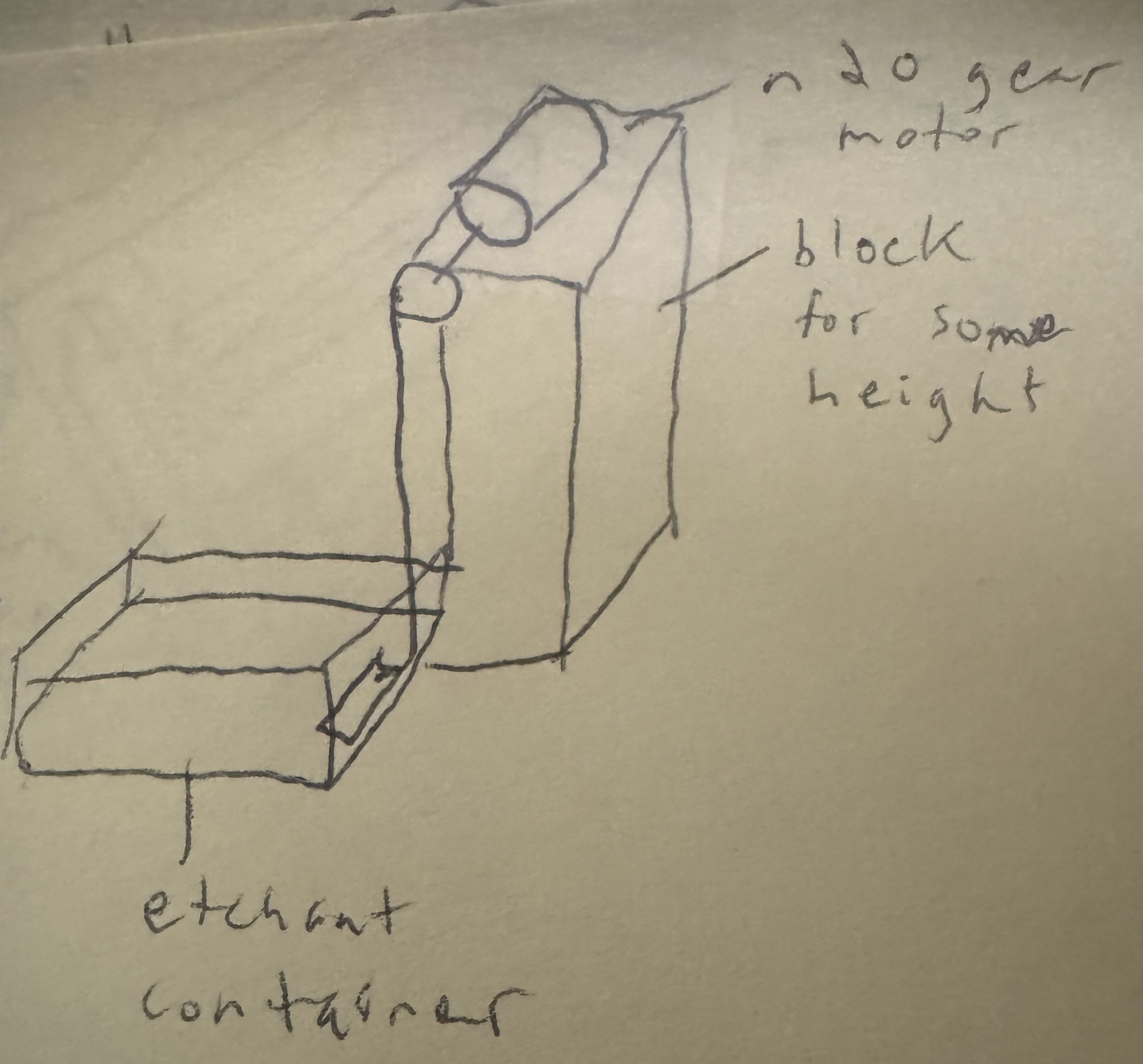
Drop a Comment: Comments: ---------------------------------------------------------------------------- Blog Post #113, submitted 1/25/26 Ok so I realized I don't have to feed in 8v+ from an external wire when I can just pull it from a neighboring pin on the chip that has 8v+ already fed to it from one of the big 8v+ copper traces attached to one of the big 8v+ pads on the underside that connect directly to one of the side pins. That side pin can then be routed to any 8v+ requiring pins if I can find a path for this routing - which I did find. So that is one less external wire input needed - bringing total external input wires needed to 3 instead of 4 as far as the 30ga wires I need to attach. So now all I need for 30ga wire attachments are 5v+ from arduino, GND from arduino, and PWM from arduino. This saves work and simplifies the wiring so its a great improvement. Oh and I also did the same thing for the 8v- feed, pulling it from a local pad rather than a external wire feed for that. 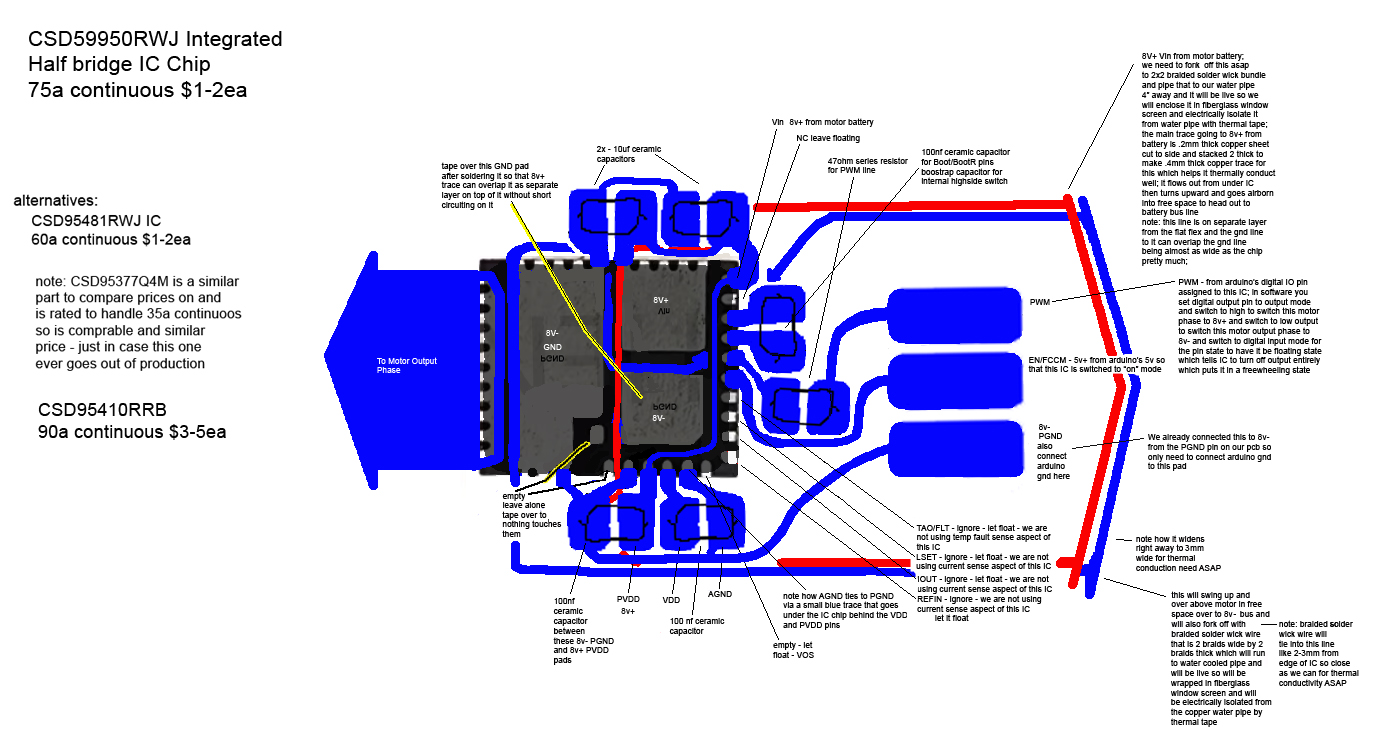
Also, I have separated out the PCB traces themselves and made them black instead of blue for printing them onto the PCB transfer paper and laminating this onto the blank Pyralux flex PCBs for etching them. I also mirrored it since it prints and laminates backwards onto the PCB. 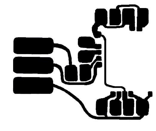
Drop a Comment: Comments: ---------------------------------------------------------------------------- Blog Post #112, submitted 1/20/26 Ok so I was thinking now that each half bridge is just a tiny IC rather than a pair of hefty power mosfets, the space taken up overall by my entire bldc motor controller is going to be about 3cm x 1cm x 2mm which is insanely small for 30a continuous at 8v motor controller! This realization caused me to reconsider whether I even need to treat this as a single motor controller cluster that has to be sat like a horse saddle onto the side of my bldc motor - my original intention for my discrete components original design for my original bldc motor controller. What I realized instead is that things are now so small that I can simply build a half bridge for each phase as a inline element nested inside the cable run leading to each phase wire of the bldc motor. So instead of having a dedicated spot for each motor controller, I'm going to have just a slight bulge in the phase wire leading out from the bldc motor and that bulge will contain the half bridge that handles that phase wire. All nested inline. This is the easiest way to implement and most streamlined I think. It also means the whole motor controller will just be "floating" in midair, not actually mounted to any motor or anything at all. Just part of the wire harness nested right in there. This is a radical approach IMO. Only made reasonable by the fact we miniaturized the design by such an insane degree. So the previous version of the schematic was intended to be mounted to the side of the motor like a horse saddle and had an l shape so inputs would come up from bottom and outputs out to left side toward motor phase wires. These L shaped half bridge setups would be stacked next to eachother side by side. In the new variation everything is inline, inputs coming from right and outputs exit out left side to motor. Here's the updated inline variation of the schematic (no longer L shaped flow like before). 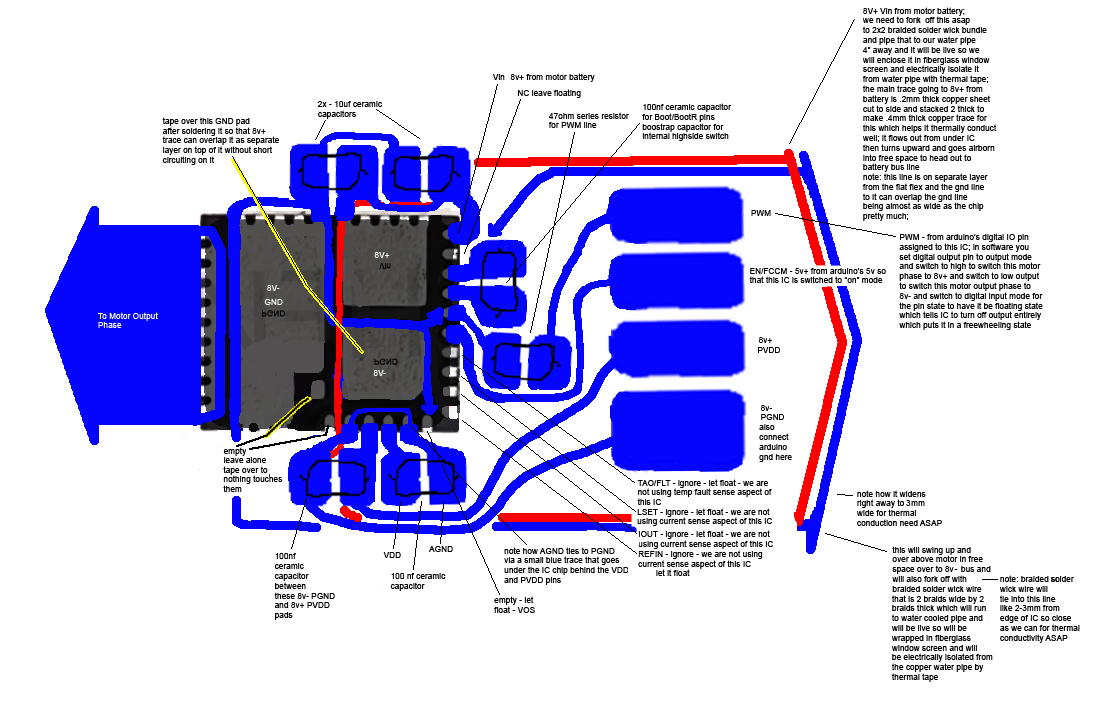
Drop a Comment: Comments: ---------------------------------------------------------------------------- Blog Post #111, submitted 1/20/26 OK, so when I was thinking of using both my discrete components motor controller design parts I already made and then also separately implementing the integrated half bridge IC design going forward, it hit me that the 8v- and arduino gnd tie together on the half bridge IC by necessity but this ruined their intended isolation I needed for my discrete components motor controller design particularly for the lowside switching portion of that schematic. On the lowside switching portion, the little mosfet has 12v- and arduino gnd tied to its source pin. If on the integrated half bridge I also have to tie arduino gnd and 8v-, then that means 12v- and 8v- and arduino gnd are all tied together always. That completely ruined the necessary isolation between arduino gnd/12v- and 8v- that I had intended to be in place for my lowside switch setup. So that was bug #1 freshly introduced that I would then need to solve for in my discrete components motor controller design. When studying this out on the discrete components motor controller design, another error hit me: when any lowside switch turned on in the design, the 12v- dedicated power supply gnd and the 8v- motor supply gnd become connected as long as that lowside switch is on. Since every lowside switch had always access to 8v gnd on its source pin, then even one moment of 12v gnd and 8v gnd attachment anywhere on the robot would cause every lowside switch in the entire robot to immediately turn on at the same time. So if any turned on, then all turned on. This was a huge oversight. For some reason since I only designed and focused on one half bridge conceptually at a time, I did not consider the effects one half bridge has on its neighboring half bridges. This just never occurred to me. I guess conceptually I envisioned that every half bridge had its own personal 12v ground from its own personal 12v supply that was electrically isolated from the entire rest of the robot. But of course that's not practical even if it is technically possible. So in testing, things did work, but would have failed as soon as I tried to test more than one half bridge at a time. So I caught this bug before testing revealed it. I discussed this horrible situation with chatgpt and it taught me that in a complex system like a robot, grounds of all your different supply rail voltages cannot be relied on to be isolated from one another like I was treating it. Even if at times they were momentarily, one switch, one change and suddenly they are not and it all becomes a common system ground again. So if I can't safely assume a ground for any given voltage is safely disconnected from the grounds of other voltages, I should not rely on switching on and off access to any particular ground to any of my lowside switches. Instead, I should be shorting the gate driver of the lowside switches to ground to shut them off rather than messing with their source pin's ground connections like I was before. I am to leave the source pin's ground connection as 12v- and its gate connection as 12v+ at all times except when I want to shut it off - at which point I short the gate pin to gnd using my logic level mosfet to do so. The fix was very straightforward and minor: I just had to add a 100ohm resistor in series with the gate pin of my big power mosfet lowside switch and then reroute my little mosfet a09t drain pin to the big lowside mosfet's gate pin instead of its source pin. The connection to its gate pin must be downstream of that 100 ohm series resistor so that the path from the big mosfet's gate pin has almost zero resistance when traveling through the little mosfet's drain line and over to its source line into ground. This way when you turn on the little mosfet, the big mosfet's internal capacitor quickly empties out, flushing into the path to ground created by the little mosfet and that discharges the big mosfet, shutting it off. When you want it back on, you shut the little mosfet off, which allows the big mosfet's internal capacitor to charge up again, which turns the big mosfet back on. So the setup now acts like a normally on relay. Note: the resistor on the drain line of the little mosfet that we used to have when it fed into the source line previously is now removed. We want no resistance on there because that would impede the little mosfet's ability to discharge the big mosfet's internal capacitor in a timely manner. We want to be able to not only discharge that capacitor quickly but also direct all incoming current from the 12v+ line that makes it past the 100ohm resistor heading for that big mosfet's gate into our ground path. This rapid redirect flushes so much of that already limited current that hardly any can make it inside the gate of the big mosfet which causes the gate of the big mosfet's voltage to approach near zero volts. So it's called a "pull down" path to ground. Attached is a photo of my schematic before and after the fix. 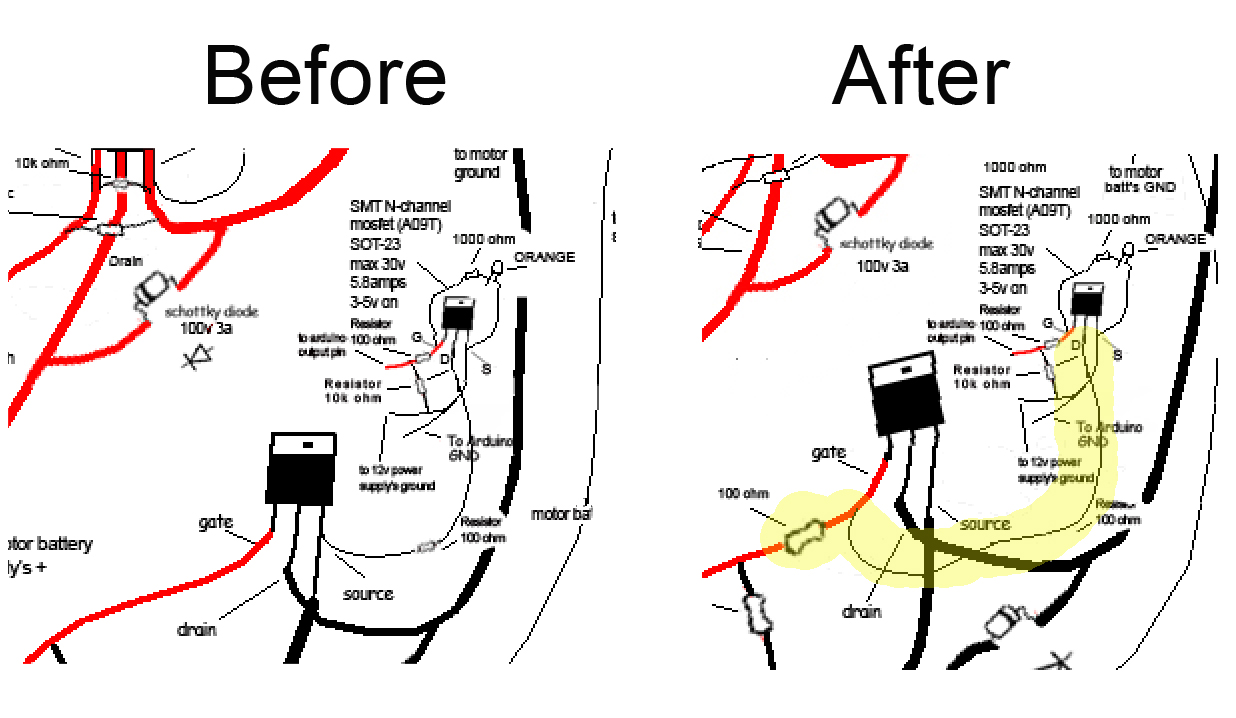
Attached is a photo of full updated schematic with the changes in place. 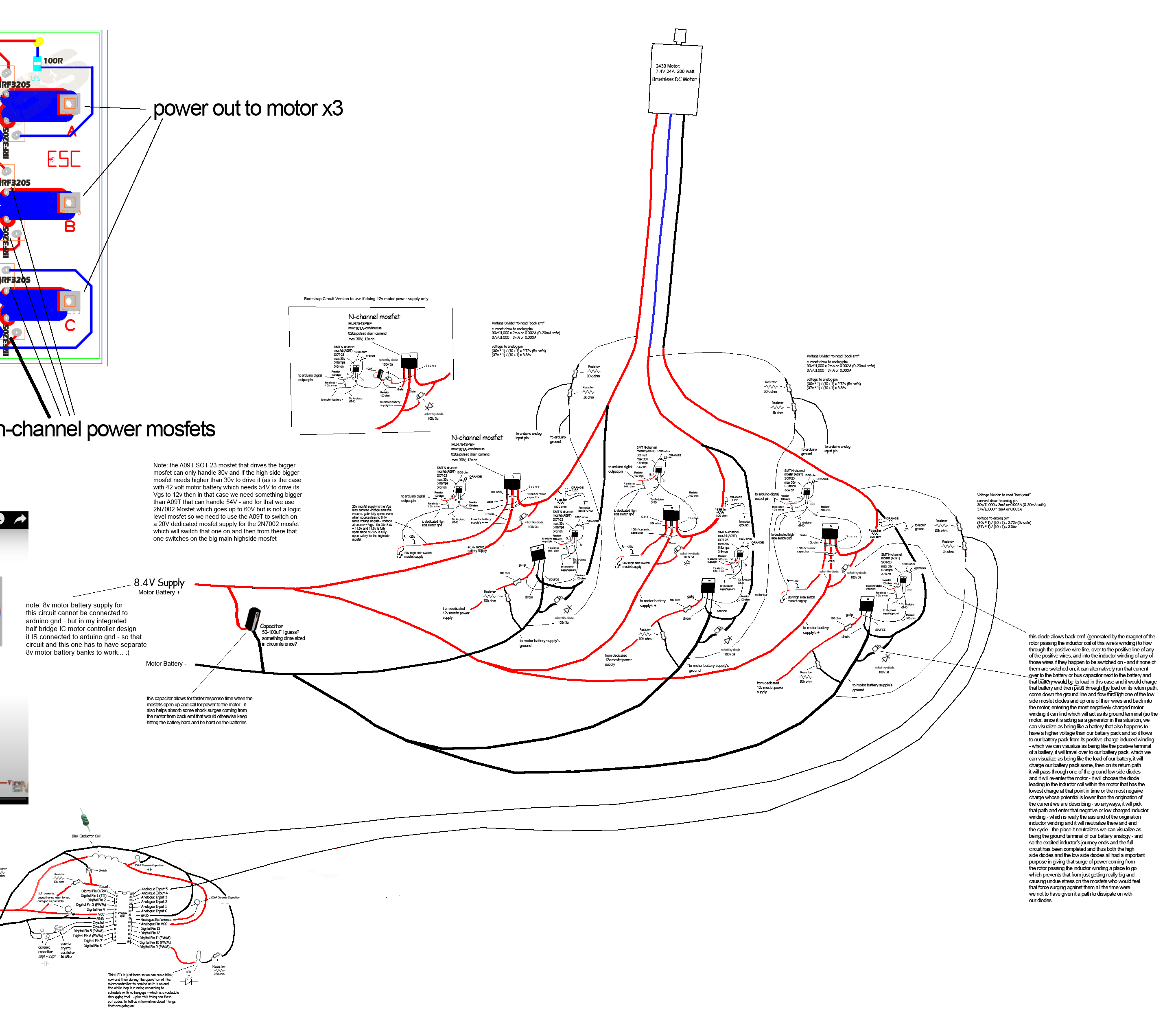
That all having been said, this discrete components original bldc motor controller design, now fixed, is worth keeping archived, but is now basically abandoned now that I have access to the time, money, and space saving shortcut of my integrated half bridge IC based design. It's kind of sad to abandon something I spent so much time on, but who knows, I may still use it if I ever come across a motor that I can't find a cheap half bridge integrated IC for in the future. It's a great schematic to have at the ready for that scenario. Drop a Comment: Comments: Older Posts |
|
|||
|
||||
| *REGISTERED NAMES AND TRADEMARKS ARE THE PROPERTY OF THEIR RESPECTIVE OWNERS. |
|
Page Hits: 53427. |