| |
|
|
|
|
|
|
----------------------------------------------------------------------------
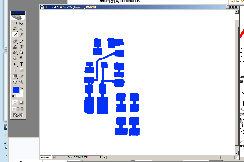
Blog Post #100, submitted 12/5/25 So armed with my successful electronic test of my prototype highside switch with driving circuit all passing, I determined now it is sufficiently validated to go through the process of converting it into a printable schematic and doing the whole DIY flat flex PCB making and acid etching process to streamline the development of the rest of the motor controller and most likely many more motor controllers as well. I opted to use photoshop as my circuit making software of choice as I'm very familiar with it and use it often. I first dropped my top view photo of my prototype circuit into photoshop then I redid its layout a bit to make it more compact, moving around copied pieces on the photo to achieve this. Next, I used the pencil tool to color in blue pads and traces connecting all the pieces of it together. I then hid all but this pads and traces layer and printed it several times, tweaking the printing scale until it fit the size of the pieces IRL. 7.5% scale was the perfect fit. 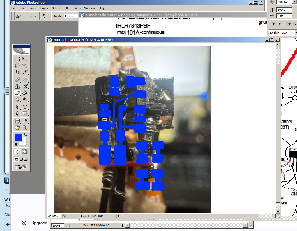
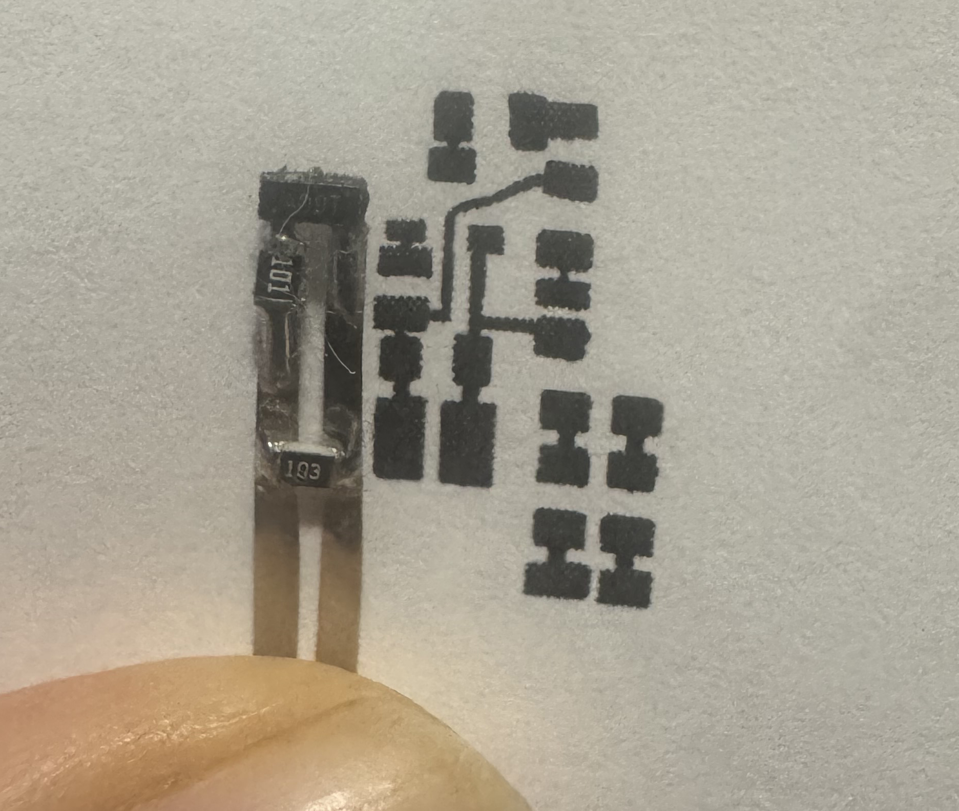
Next, I will need to refresh my knowledge of the transfer paper print and transfer of the ink off of this paper onto the copper clad blank flat flex PCB and then acid etching away all unwanted copper and then removing the ink to reveal the fresh copper traces and pads. Then I can solder all the SMD components onto this. Heck I may even make a solder paste stencil and place components and bake them on. But perhaps just hand solder for now? Not sure. The former is faster in the long run but takes more setup and is quite committing. I'd rather validate my designs even further before going that far. Drop a Comment: Comments: ---------------------------------------------------------------------------- Blog Post #99, submitted 12/4/25 I just tested the positive high-side switch portion of the motor controller and everything seems to be working as intended. The section including all parts involved is circled in a bold blue line to indicate the portion I just tested successfully. 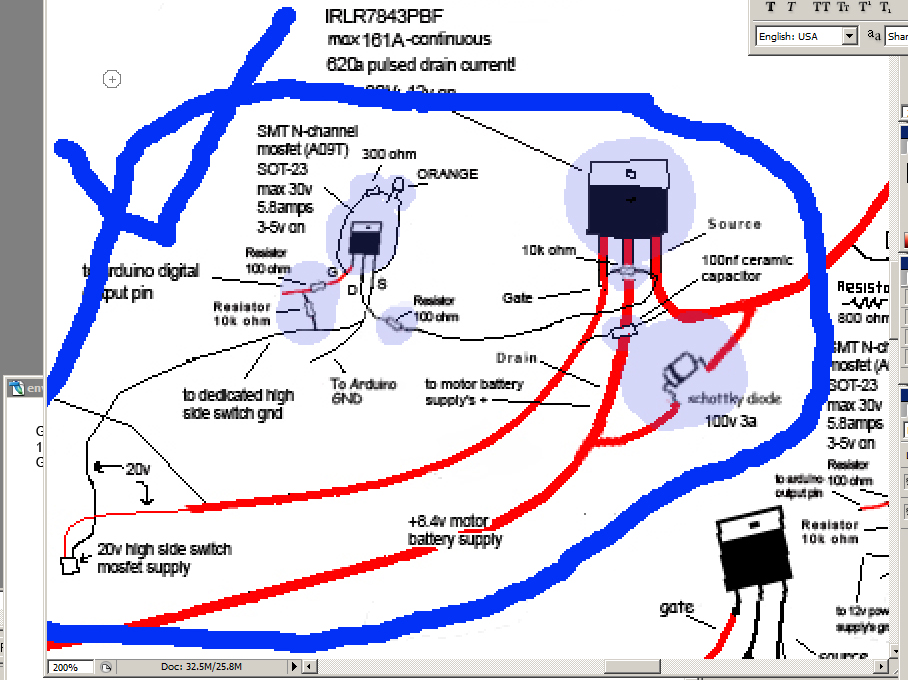
One issue I'm having though is that the drain of the A09T attaches to the 100ohm resistor tightly and is a weak point that broke off twice now. Hardly any wiggling at all on the arduino input line and ground line leading into the A09T mosfet causes the drain solder attachment to break off. I am wanting to glue it all down onto the mosfet but I'm supposed to tape the heatsink on under all this stuff so I don't think I should glue it down. I need some kind of backing sheet to glue things off onto (where a PCB normally does this job). Which will provide much needed strain relief at all attachment points. I guess I'm learning the hard way why PCBs are used in general. Without a flat backing plate or substrate of some sort the attachment points between components are vulnerable to flex and breakage super easily. This surprises me. 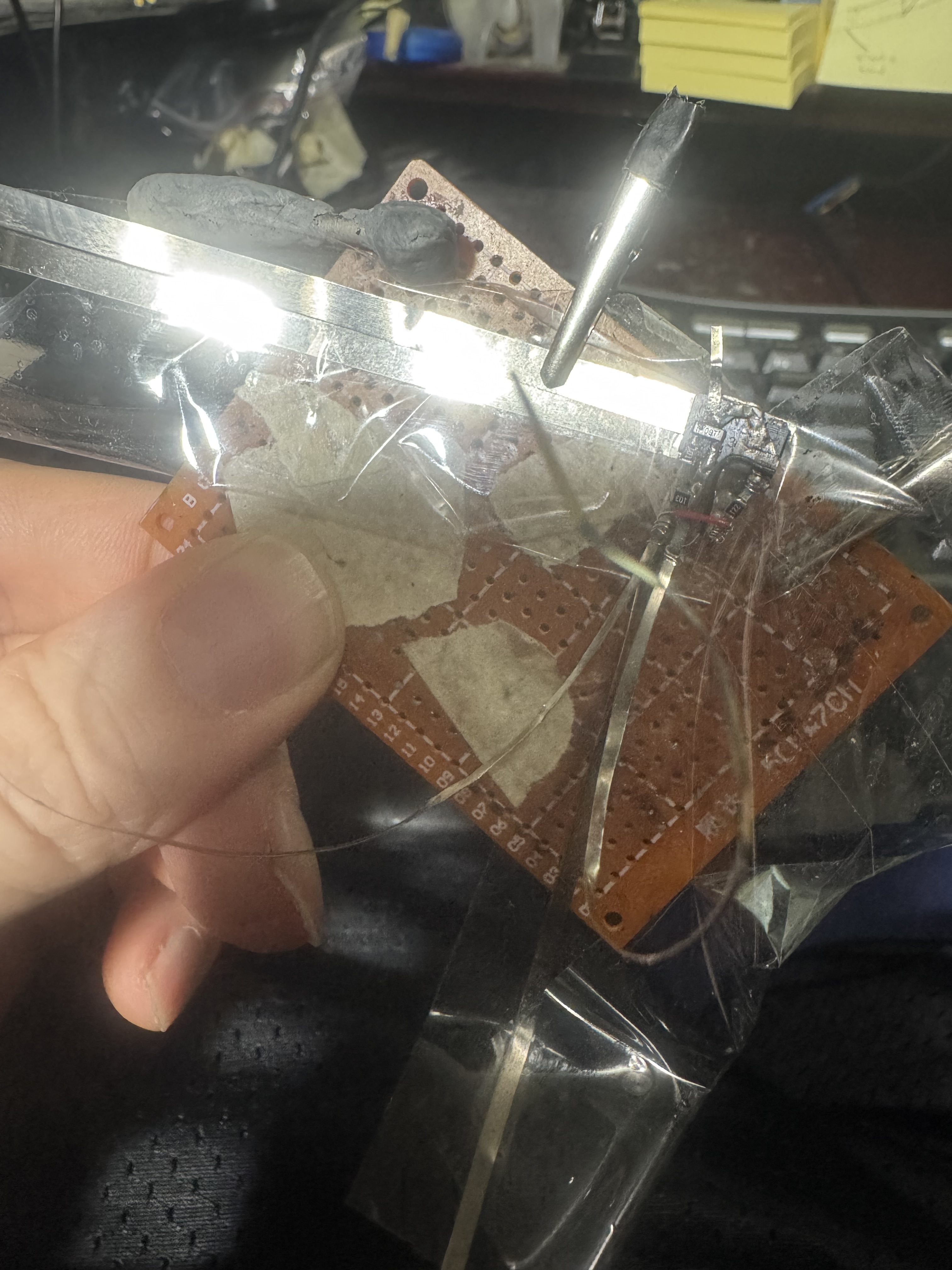
To perform the test I used one lab power supply set to 20v and one set to 8.07v and used a 18650 lithium battery as the 4.12v to simulate the arduino output pins. I carefully electrically isolated all the metal lines with packing tape for now to ensure no short circuits and then I connected the lab power supply pins to the correct locations with alligator clips. Finally I connected the 18650 lithium battery 4.12v to simulate the arduino turning on the A09T mosfet - I did this using the two nickel strips for this portion joined to the battery with neodymium magnets. If I had a 3rd power supply I could get 5v off of I'd have done that but I didn't have one in arms reach so the battery it was. The LED came on and I tested the output line to the motor was indeed 8.07v. I then disconnected the + side of the battery and verified the line going to the motor was 0V. It was - although if I kept the multimeter on that line longer I noticed it would creep up to like 3.4v but something similar happened on my last test run and chatgpt said this was like parasitic capacitance involving the multimeter or something and nothing to worry about. The main thing is it would START at 0v when I first connected and then rise up to 3v or w/e over time on the multimeter screen and this behavior was ok last time so meh. We're good I think. Where to go from here then? Well I'd say I make the other (lowside) portion of the half bridge and then test the full half bridge to ensure it's all working. I think then my design is validated enough to move into diy flex pcb for some of these portions that are on the layer that goes onto the main beefy mosfets. Drop a Comment: Comments: ---------------------------------------------------------------------------- Blog Post #98, submitted 11/11/25 Okay so here I have attached the LED and resistor pair with their 30ga wire wrapping wire onto my highside mosfet's front face. I may add conductive silver paste to the wire wraps in the future if any issues come up there. However, I am wondering if just tightly wrapping it in electrical tape would more or less guarantee the connection doesn't open circuit. We'll see. 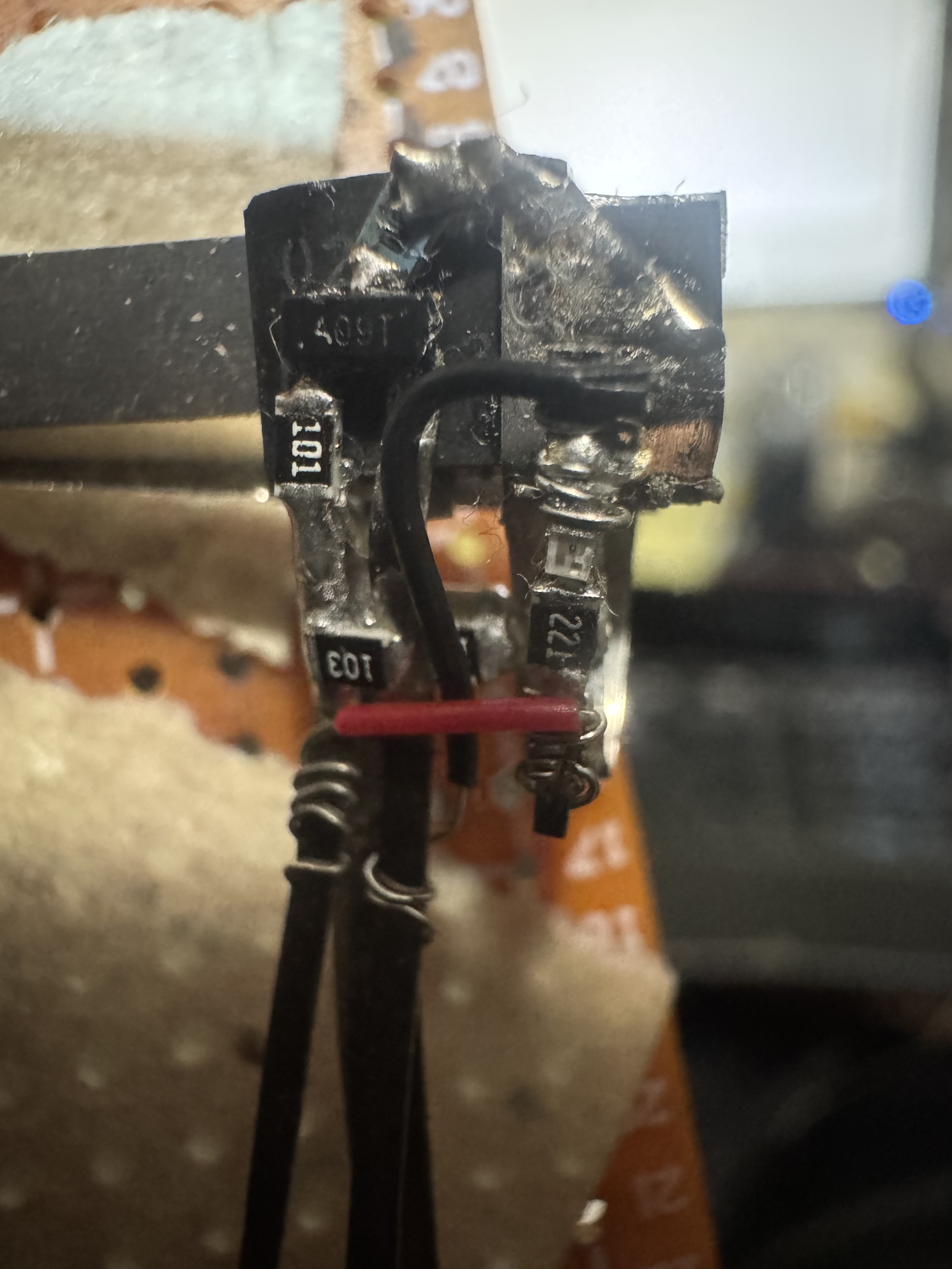
I also finished soldering together six braided copper solder wick strands which will act as my heatsink for my highside mosfet. I am still deliberating on how to attach it to back of mosfet in such a way that it will be electrically isolated but thermally conductive. I am leaning toward thermal tape for this. 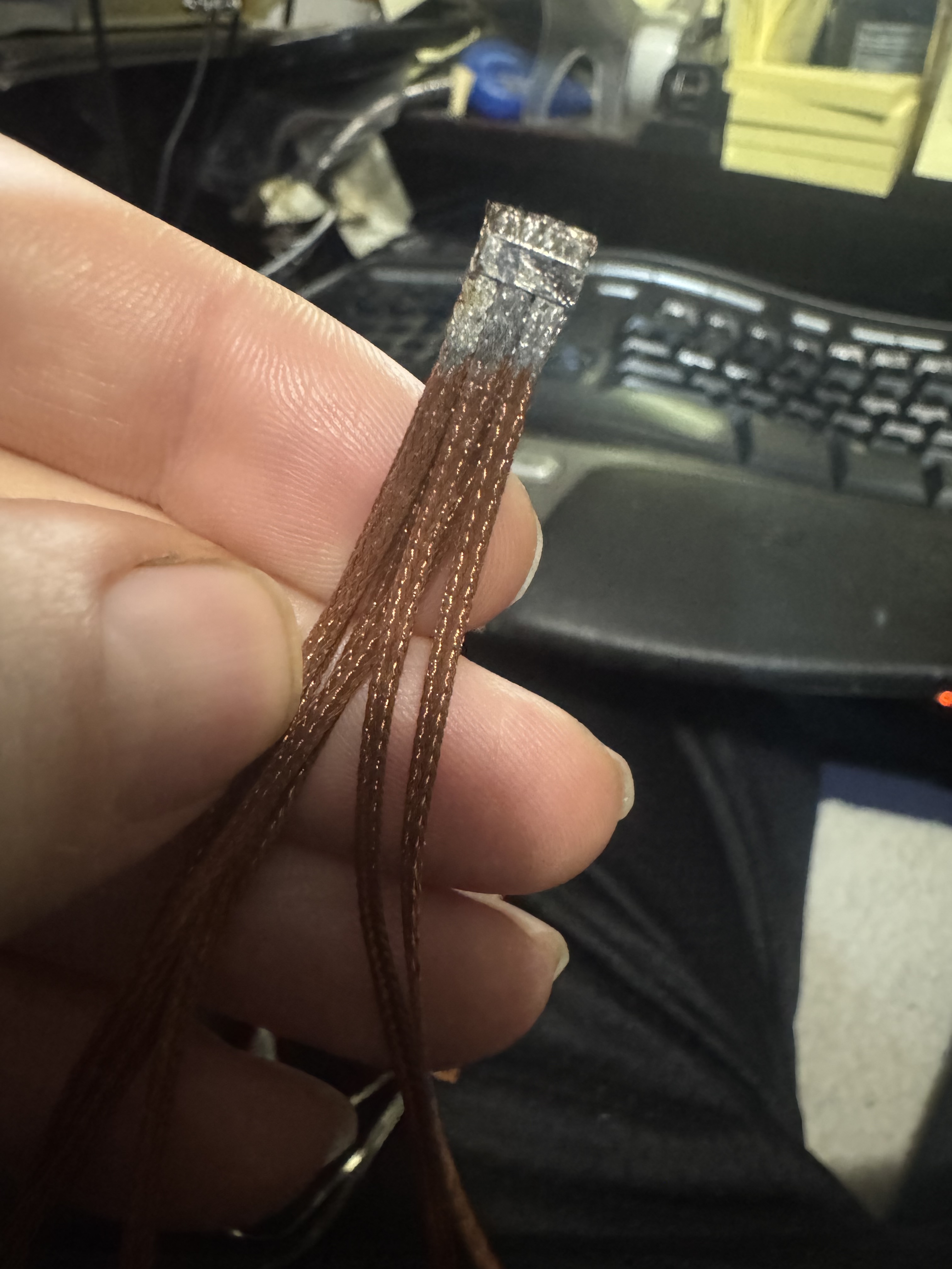
Drop a Comment: Comments: ---------------------------------------------------------------------------- Blog Post #97, submitted 11/7/25 Couple updates: An audience member redid my brushless DC motor schematic in the traditional commonplace formatting which for most is easier/quicker to read and understand due to familiarity. So I'm reposting it. It looks mostly accurate although I have since added a 100nF ceramic capacitor between the gate and source of the highside mosfets to reduce ringing issues. Standard practice according to chatgpt. I also changed the LED color to orange because chatgpt said blue would show through the silicone skin more and add a cold inner glow and we want it to look like real skin so no blue. As to why the highside mosfets get a 100nF ceramic gate capacitor but not the lowside, here was how chatgpt explained it to me: -High-side MOSFETs: Their source pin moves up and down with the motor phase (it's not at a fixed potential). During switching, the drain and source both move rapidly, and the gate voltage must track that movement precisely - any ringing or inductive noise can momentarily over-stress Vgs. That's why we add the small capacitor across gate and source: it tames that high-frequency ringing and helps hold the gate steady relative to its moving source. - Low-side MOSFETs: Their source is solidly tied to ground, so the gate always swings relative to a fixed, quiet reference. They don't experience the same "floating" gate drive or large dv/dt transitions on the source pin. So, the gate is inherently more stable, and you don't need that extra 100 nF G-S capacitor. Anyways, here is the audience member schematic: 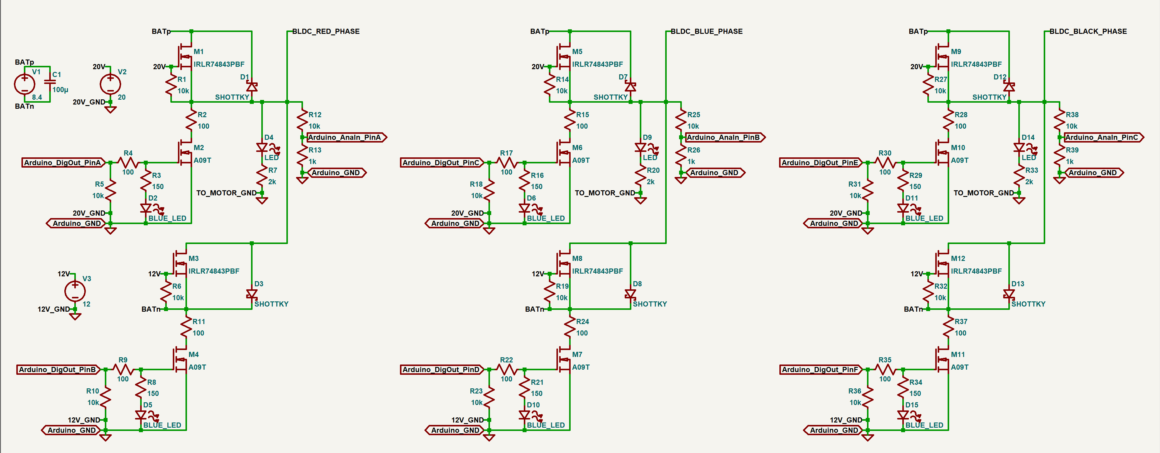
Here is my updated schematic with the changes I mentioned: 
In further news, I tediously installed the new 100nF ceramic capacitor between gate and source of the mosfet. Due to the close proximity to the 10k ohm Vgs resistor and various other low temp solder joints in the immediate vicinity, any heat applied would surely have caused those to desolder and the whole thing to start falling apart so I ended up just soldering nickel strips to either side of the 100nF ceramic capacitor (by itself off to the side) and then used the tip of a sewing needle to apply a tiny amount of conductive silver glue onto the gate and source nickel strips coming off the IRLR7843PBF mosfet and then pressed the nickel strips of the ceramic capacitor into that. I put that in front of a mercury vapor bulb for an hour or so to cure and then applied another generous helping of conductive silver glue over the top of the joint. I then baked that another 7 hours under the mercury vapor bulb again. This photo shows the final result. 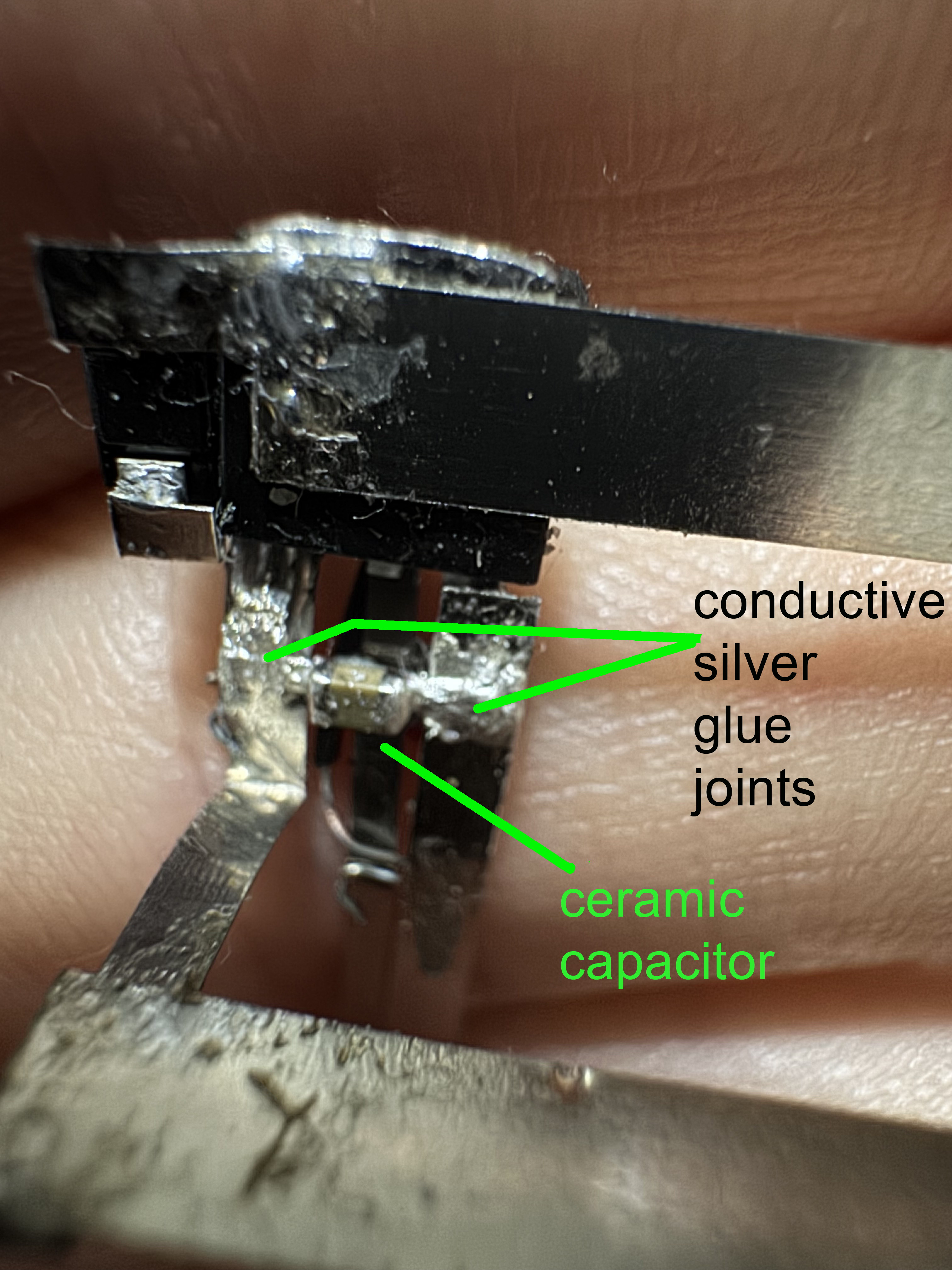
It appears to be a solid joint and I think this is a great way to make attachments when you can't use soldering! It might even be better than soldering in some cases from a ease of application perspective but not sure yet on that. Drop a Comment: Comments: ---------------------------------------------------------------------------- Blog Post #96, submitted 11/2/25 Ok so I decided to use 30 gauge wire wrapping wire and wire wrap that onto my nickel strips that I connected onto my LED setup then trim off any excess nickel strip. What I like about this is this wire is very fine so it takes up hardly any space and by being able to wrap it on I did not have to apply heat which could have desoldered my smd components by accident. I also like that it is already insulated and color coded so I don't have to worry about insulating my nickel strips the whole run to wherever this connects. To insulate the whole LED contraption here I used packing tape so I can see all my components well but still have them electrically isolated. I just folded the packing tape over the whole assembly like closing a book over a bookmark. 
note: after wire wrapping the wire wrapping wire I noticed it was not that tight on there. I did not use a wire wrapping tool because I lost mine so I just used needle nose tweezers to manually wrap it around and around. Anyways to tighten it well I just crimped it with the tip of my wire strippers that has some kind of toothed pliers that crimps things well. After doing that the connection appears very solid. Drop a Comment: Comments: ---------------------------------------------------------------------------- Blog Post #95, submitted 10/21/25 Well I finally got back to the electronics after about a month long detour real life interruption. All kinds of stuff slowed my progress on this session. But I got stuff done nonetheless. 0603 LED to 0805 resistor and some nickel strip leads coming off. Tested and working. This will be the indicator light for when the lowside mosfet comes on for one section of the custom BLDC motor controller. 0603 LEDs are extremely tiny for hand soldering and they don't take solder well either. I was originally going to go with blue LEDs but chatgpt said that would give off a unrealistic color through the silicone skin so orange would be better to give a more natural and less silicone skin piercing indicator light. Somehow I ran out of 470ohm resistors so I had to order more and I used my 200ohm ones instead for now. Which are a bit too bright. But chatgpt said I can diffuse the LED with a glob of silicone tinted black to darken and diffuse the light it gives off which sounds like a good idea to me. I am planning to use wire wrapping wire to come off of this assembly and tie into things. Somehow just attaching these two parts and testing it took me almost 3 hours. Between studying the schematic to refresh my memory on what is going on, visualizing placement options, overheating and destroying one LED, trying to locate the right color LEDs, shopping for replacement 470ohm resistors, researching and substituting in 200ohm resistors, discussing LED color options with chatgpt, figuring out how to solder a 0603 LED directly to a 0805 resistor part to part by hand, accidentally breaking a part off of its nickel strip lead and having to redo the connection, etc etc. All of it just crawls. Hard to stay patient with electronics sometimes and I do things in inefficient ways often. Learning what can and aught not to be done is tough from a patience perspective. But I insist on trial and error and experimentation which takes time. I just need to get into a daily habit to stick with it till completion. It's all complicated. Trying to figure out how to electronically isolate it all next. Thinking of using lamination plastic taped around it all so I can still see it all and visually troubleshoot. Also I'm considering how I can use solder wick braid as a heat pipe for each mosfet and run that over to the liquid cooling system. But it can't conduct. So thermally it can conduct but electrically it can't. Trying to figure out whether to create a barrier of micah or just thermal silicone for this and the routing needed. Also considering if I need mini coaxial shielded cable for the wiring of each or just regular wire wrapping wire when going from microcontroller to mosfets etc. Also trying to figure out if I need hall effect sensors or back emf reading or no feedback but my potentiometer and the implications of each option. Just so much to consider in all of this. And all of those considerations also slow things down even more as I have to make decisions on it all. It's quite overwhelming. 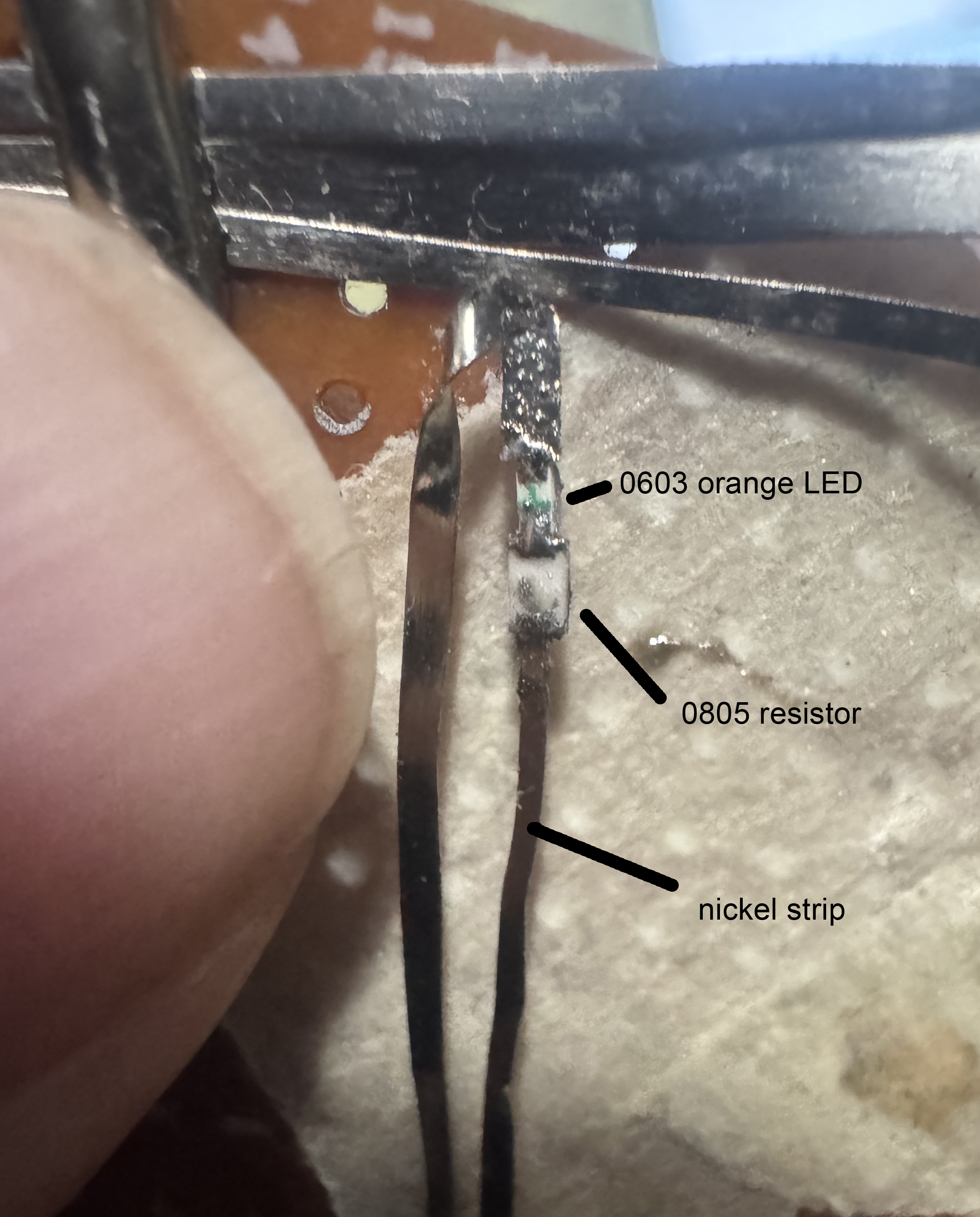
Drop a Comment: Comments: ---------------------------------------------------------------------------- Blog Post #94, submitted 9/19/25 I started some testing on some subsections of the BLDC motor controller and ran into some problems and learned several things. I'm working with chatgpt to resolve each issue and have been updating my schematic to reflect alot of the changes I am making. One thing I learned is that for the high side switch, the voltage from gate to source has to be 10-12v higher than the drain voltage because the drain voltage becomes the same as the source voltage once the switch is on. The voltage from gate to source then either has to start out as motor input voltage + 12 while still fitting within the voltage from gate to source max allowed voltage as stated by the datasheet or it has to rise dynamically as the source voltage rises such that the voltage from gate to source is 12 more than the source voltage as the source voltage rises to become the drain voltage. Fortunately, I can have the former for this 2430 motor since I can use 6-8.4v to supply the motor and the voltage from gate to source max value is 20v. This means I can use voltage from gate to source of 20v and this, when mosfet is first switched on, does not fry mosfet but as the source rises to become 8.4v, 20v-8.4v is still 11.6v which is sufficiently high to enable the mosfet to still stay on without anything dynamic set up. If I want to go with a 12v motor supply on some of the bigger motors later on, I will need a bootstrap circuit to supply the highside mosfet with a dynamic voltage from gate to source that rises when source voltage rises. So I added that schematic diagram to this as well as an option. I also can use a mosfet driver for this but was hoping to cut that cost and added volume taken up by just using discrete components rather than a IC for this. Anyways, to break things down even more in testing, I decided to just test turning on and off a single highside mosfet using a pair of lab power supplies, one to provide 20v and one to provide 8.4v. To turn on I connected the gate and source to my 20v lab power supply and I connected my red alligator clip of my 8.4v lab power supply to the drain and then measured from source to the black lead of the 8.4v power supply and verified 8v on that test which worked - proving the mosfet was in fact on. I then removed the black alligator clip of the 20v lab power supply from source and shorted the source to the gate to drain the internal capacitor inside the mosfet and then tested from source to the black 8.4v clip and sure enough it was near 0v so was off. But it did gradually climb back up to 8.4v after the short from gate to source was removed due to capacitive coupling and leakage according to chatgpt. So I will need to add a 10k ohm resistor between gate and source pins to short it automatically and keep it fully drained and off fully when it's supposed to be off. So I plan to just gradually add components little by little and test after each thing is added to ensure it is working right still after each little change and this way gradually build out the circuit, proving each thing works as we go. This is because things have all these gotchas and "oh you didn't know this little detail?" that keeps coming up and proves it was more complicated than I thought. So I just have to prove every little thing as I go. To try to find out what is wrong after the whole thing is built would be WAY harder than to figure out what went wrong when a single component is added and it was working before said component was added. So that's how I will be able to overcome this challenge best I feel. Note: Reminder: I am building a custom BLDC motor controller because an off the shelf one would not have enough miniaturization to fit into the tight space constraints I have to work with. Also, building my own gives my software more precise control of every little advancement of the rotating magnetic field and along with that I'll have the ability to PWM the advancements to make them more smooth, less noisy, and have torque control as well this way which means the fingers can be rough and fast in movement as needed or slow and gentle and dainty or slow but powerful etc. I can also create acceleration profiles that match human finger joint acceleration in order to have the movements look very natural just like a human's movements which is very important to me. Just alot of fine precision is possible when its all my own circuit I feel. While off the shelf ones may have some of this functionality, the price often reflects that and is then prohibitive. But in any case nothing is off the shelf with this level of control AND the ability to so finely tune its form factor and volume envelope to fit my exact needs in space on a per motor basis. 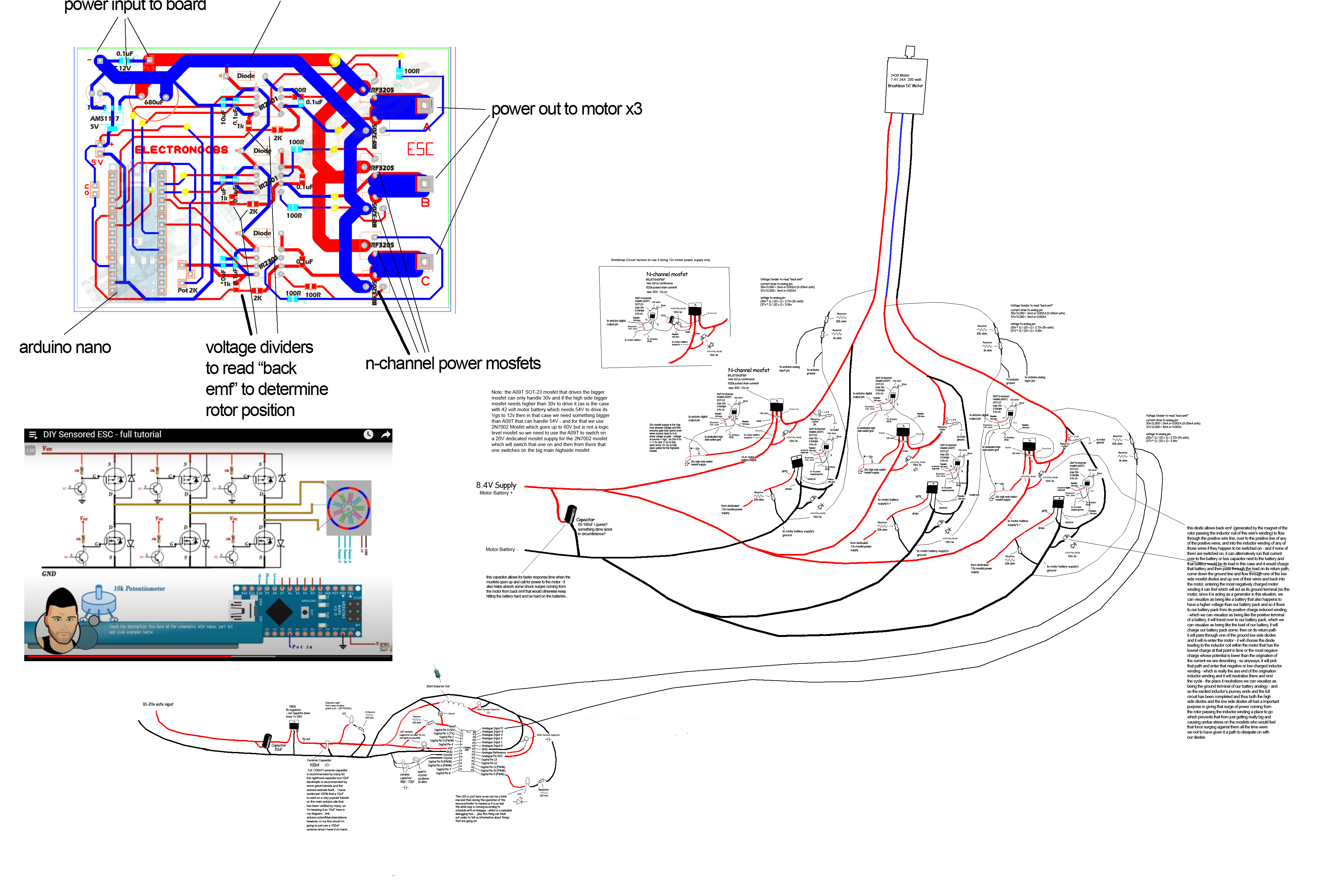
Drop a Comment: Comments: ---------------------------------------------------------------------------- Blog Post #93, submitted 9/10/25 Back on the electronics again. Have been going over my BLDC motor schematic and making some little tweaks to it. Here's the updated schematic. It's a combination of lots of other schematics I've found online as well as some chatgpt help. With 1 being no clue and 10 being absolute expert tier in BLDC motor schematics I'm probably a 5 IMO. So take my design with a grain of salt. It will be very fun to see if it works. Note that I put a couple schematics of Electronoobs - a great youtuber on the left hand side as reference and study material. My schematic is the big one on the right. Electronoobs series of videos on BLDC motor controllers has been extremely helpful in me forming a rudimentary understanding of this stuff. 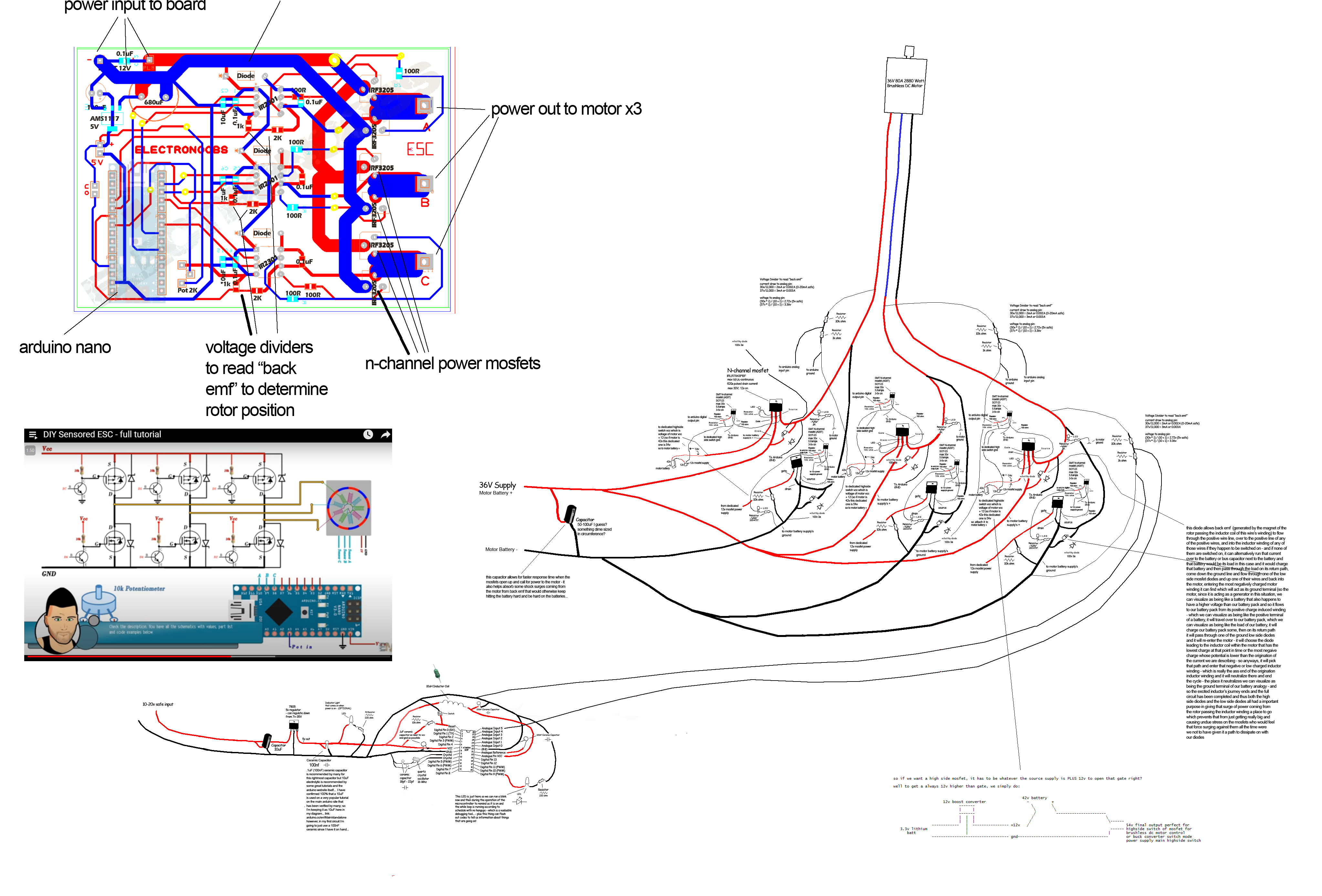
Drop a Comment: Comments: ---------------------------------------------------------------------------- Blog Post #92, submitted 9/6/25 I installed two tensioners for the robot and they were seriously successful overall in testing. So much so that I am now confident enough in the entire pulley system to move onto the custom mini BLDC motor controller to get the motor to run motorized tests of finger movements next. Well after a couple very minor tweaks that is. So the first tensioner I installed on the extension part of the index finger joint we are working on. I used the bracelet cord folded in half and fishing crimp sleeved then sewn into the bone fabric. It seems just about perfect except for one thing: I want to keep it under mild constant tension but the bone fabric creeps/moves slowly when put under constant tension like this because it is taped into place on the bone after all. The tape is allowing the movement. This means it does not stay put and my anchor points move over time so I can't set a tension and rely on it staying at that tension long term. To resolve this I need a mechanical connection at the tension point anchoring location. 
To mechanically connect my anchor point, I have decided to use tiny self tapping screws. I have avoided screwing into the bones till now but I'm making an exception here. The screws won't be going that deep and the finger bones are unlikely to break anyways IMO. So I feel comfortable with this. Here's the screws I ordered for this from Amazon: 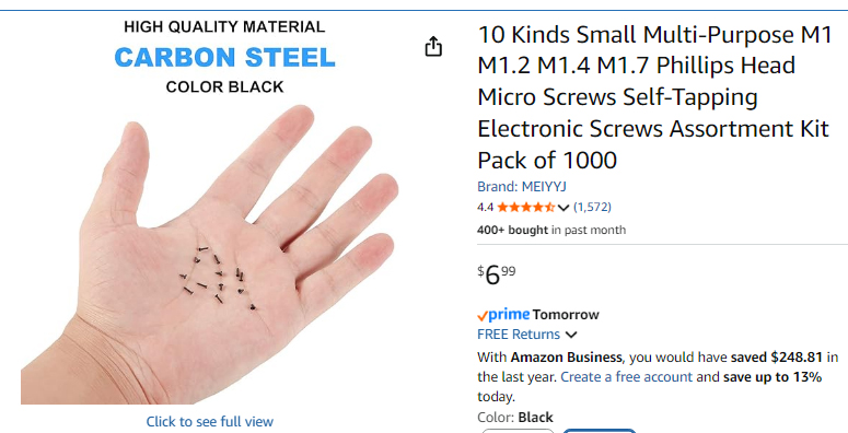
Next, I created a tensioner for the middlemost archimedes pulley. That pulley was creating significant drag and slowing down the finger extension during testing due to rope friction. So adding a tensioner line to pull it back down toward the fingers during extension was my solution for this. It worked amazingly well. To make this, first I tied off a fishing hook eye to the bottom of the radius bone just above where my TPFE guide tubing entrance is. Then I glued a 7cm piece of bracelet cord to a piece of 6lb test .08mm braided pe fishing line with 401 glue. I secured the top of the bracelet cord to the top of the archimedes pulley system and then threaded the other end through the fishing hook eye and back up and to the bottom of the archimedes pulley where I tied it off. So it ties off at top, comes down to bottom, goes through the fishing eye then comes back up and connects to my pulley. It creates just enough downward pull to delete the rope drag slowing down that pulley from coming down and this enables the system to unwind and extend back to its starting point after each time I contracts/pulls upward to cause finger contraction. This means the finger extension now happens swiftly with no hangups and the whole archimedes pulley system is now under constant tension at all times which keeps things neat and prevents tangling issues pre-emptively. This rig was a massive success and took up hardly ANY space at all. I put the post it notes behind the archimedes pulley tensioner so you can see it. It's hard to see otherwise without a contrasting backdrop. It works amazingly well. 
Drop a Comment: Comments: ---------------------------------------------------------------------------- Blog Post #91, submitted 9/6/25 Okay so the bracelet cord self untied quickly so I'm going back to my previous approach of tying off both ends of the bracelet cord with a fishing crimp sleeve. While trying to cut in half fishing crimp sleeves with my mini miter saw I noticed it was a difficult process and not ideal. So I came up with a easier method which was way faster, cleaner, less setup and takedown, no deburring needed, etc! The method is to lay the fishing crimp sleeve on a flat surface and line up a exacto knife blade perpendicular to it across its top and then apply moderate downward pressure to score the metal and then slide the knife carefully back and forth creating a perfect scoring line that grows deeper with each pass. After several passes the fishing crimp sleeve halves separate cleanly! This method uses a similar principle to a copper pipe cutter used in plumbing. 
Drop a Comment: Comments: Older Posts |
|
|||
|
||||
| *REGISTERED NAMES AND TRADEMARKS ARE THE PROPERTY OF THEIR RESPECTIVE OWNERS. |
|
Page Hits: 53440. |