| |
|
|
|
|
|
|
----------------------------------------------------------------------------
Blog Post #110, submitted 1/18/26 Well I deep dove into the CSD95481RWJ IC route. I estimate it will cut the work in half roughly for every motor controller made and cut the size taken up by about 60% compared to my previous discrete components approach. Now I will note that I did come across the BTN8982TA which is rated to 40v and can handle 30a continuous 50a peak short burst. But it's TO-263 form factor so about 4 times as big as the CSD95481RWJ. It also costs about $2 each so double the price. It's not a bad option though all things considered but just not quite as good as the CSD95481RWJ for the reasons mentioned. I note it here so I don't forget about it. It can be a great option if the CSD95481RWJ doesn't work out in the end or something. Also of note: CSD95377Q4M is a similar part to compare prices on and is rated to handle 35a continuos so is comparable and similar price - just in case this CSD95481RWJ IC ever goes out of production - this one will easily step in to fill its shoes! Anyways, for the thermal concern - which is my biggest concern, I plan to top cool the CSD95481RWJ using a .2mm plate thermal siliconed into place on top of the CSD95481RWJ and then solder a bundle of 4 braided solder wick wires to that and run that off to the water cooled copper pipe about 4" away. The top cooling only handles about 30% of the cooling according to chatgpt. The most important 70% is from the bottom cooling through its pads on its bottom. For this I plan to use double stacked .2mm thick copper plate soldered to its IC pads. So that's .4mm thick. Also it will be around 2mm wide where it attaches to the pads. It will then route out from under the chip and swing upward into free space and head over to the 8v+ and 8v- buses coming from the 8v motor battery banks in the robot's lower torso. These thick copper traces I will fork off of with braided solder wick wire right near the CSD95481RWJ IC chip for thermal conductivity reasons. This braided solder wick wire will be live so I will wrap it in fiberglass window screen so nothing can touch it - preventing short circuits. It will then be electrically isolated from where it connects to the water cooled copper pipe with thermal conductive tape. The braided solder wick wire attaching to these thick copper traces will be a bundle of 4 per trace. The various decoupling capacitors this chip calls for I will connect to its output pins using flat flex PCB DIY hand made. I'll be attaching this PCB first and attaching the thick copper traces to the underside pads second as a separate layer that goes underneath the flat flex PCB layer. The flat flex PCB layer will mostly stay around the outsides of the chip and have its center cut out and removed - the part of it that would get in the way of the underside main pads under the chip. So the flat flex PCB will just hug the outsides of the IC mainly in a U shape around the chip leaving the center of the bottom of the chip free to solder to with my thick copper traces. Note: the thick copper traces will be cut out with scissors from a roll of .2mm copper sheeting I bought on amazon which I mentioned a few posts back. Double stacking it wil double its thickness and increase its conductivity both electrically and thermally. Note: in a usual setup with this CSD95481RWJ IC, a multilayer board with a array of vias is used to bring the heat downward off the chip and into another lower layer within the multilayer board where it can then radiate on said layer outward in every direction. In my approach, I use thicker traces than the layers of a multilayer PCB has so I have alot more local copper in play. Then instead of the heat transferring down and then outward in all directions on very thin copper, mine travels down then in a single direction outward away from the IC on that trace. The trace will need to be as wide as possible as soon as possible. I expect to get it from 2mm width - the width of the pad - to 5mm width within a few mm. This rapid transition to a wider width combined with the use of much thicker copper compared to a multilayer PCB's copper thickness of its layers means I should be able to exceed the thermal performance of a multilayer board using my approach. Especially since I also plan to quickly fork off the main traces with bundles of 4 solder wick wire braids that will carry the heat off to a water cooled pipe 4" away. Note: in my attached schematic I only show a single CSD95481RWJ IC because they are all wired up the exact same way. It's just doing it 3 times for each of the 3 phase wires of the BLDC motor. Note: I will use a single electrolytic capacitor per motor controller also not pictured in the schematic. 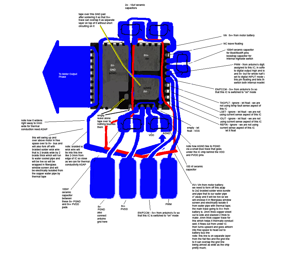
Drop a Comment: Comments: ---------------------------------------------------------------------------- Blog Post #109, submitted 1/16/26 I was randomly talking to chatgpt about how I have been feeling burdened by having to make my own BLDC motor controllers for my robot lately and it randomly mentioned integrated half-bridge power modules as something I could use to cut down on my labor load in making these motor controllers. This immediately stood out to me as something I'd never heard of and something intriguing. I have so far been working on my lowside switch and highside switch which together form a half bridge. Many solder connections have been involved and alot of discrete components are involved. The concept of an integrated half bridge on a single chip - meaning two big power mosfets and all the drive circuitry for those power mosfets all condensed into a single chip would be a huge reduction in size and component count as well. So I researched if any are able to do 8v 30a for my 2430 BLDC motor's needs. Turns out there are some out there. At first I was looking at Texas Instruments CSD95377Q4M Half-Bridge Driver (30?A) which can do 30a continuous so perfect for me. However, I didn't want to lock myself into a single vendor chip that may one day be discontinued. I prefer something ubiquitous with many competitors making it that can be purchased from aliexpress. Something commodity level. This way I future proof it and don't have to worry about any one manufacturer discontinuing parts I'm using and prices soaring because of that or simply the part becoming unavailable. So after a bit further digging I found CSD95481RWJ QFN chipset on aliexpress sold by several vendors and one was under $1 each. So it is equivalent to two power mosfets plus all drive circuitry for each power mosfet all for under $1. This one also has 60a continuous rating. It is only 5mm x 6mm in size which to me is insane. This is so much smaller than the setup I've been working on yet just as powerful. They are usually used for tiny buck converters and used directly on videocard PCBs and in servers and in automotive PCBs and much more. In any case, using 3 of these half bridge chips you can drive a BLDC motor. The consolidation of so many parts into such a tiny package is truly blowing my mind. So I ordered 60 of these chips - enough to drive 20 BLDC motors. I am leaning toward using these for all my motor controllers if working with them is easier than working with discrete components like I have been. They are cheaper to work with I think - I'd have to run the numbers on that though. They even have built in temp sensing we can read in which is a bonus. Their built in current sensing will not work for BLDC motors so I'll still need my shunt resistor current sensing circuit setup external to it but that's ok. All in all these appear to be a game changer in terms of reducing part count so less potential points of failure and also reducing board footprint so miniaturizing my electronics even more which is very good for us. I'm still needing to work out now how I want to hook these up in terms of PCB making for it and any discrete external components needed to support it. It is also top cooled which is interesting. I'm envisioning using silicone thermal adhesive to glue on a copper pad that has my braided solder wick wires already soldered to it. These will carry the heat away to my water cooled pipe system. 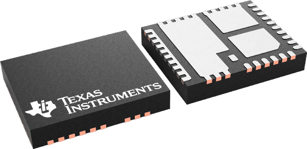
I'm kind of amazed that nobody really seems to use these for BLDC motor controllers. They seem perfect for it. Maybe I'll start a trend. Assuming I don't find out the hard way why they are never used for this application! note: the full product title: "(5pcs)100% original New CSD95481RWJ 95481RWJ CSD59950RWJ 59950RWJ QFN Chipset" note: for my previous BLDC motor controller design I was needing to use 6 digital IO pins to drive a single BLDC motor controller's 6 power mosfets by way of their control circuitry. But for a BLDC motor controller design using 3 CSD95481RWJ H-bridge chips, I will only need to use 3 digital IO pins on the microcontroller. These CSD95481RWJ H-bridge chips use a pwm pin that is a tri-state pin - you can have high, low, and floating as the signal you send to it from your microcontroller. Digital output high and low are the usual digital output modes but the floating mode you do in your code by configuring the pin to be a digital input pin which makes it a floating pin. These 3 states fed into the chip makes it either give you V+ as its output or V- as its output or just off/floating as its output. This corresponds perfectly to the normal h-bridge 3 states we'd be using with our discrete components previous microcontroller design. So this savings in total digital I/O pin usage on the microcontroller means you can drive more motors per microcontroller in theory which is pretty cool. Drop a Comment: Comments: ---------------------------------------------------------------------------- Blog Post #108, submitted 1/3/26 So I did manage to add a pair of braided solder wick wire as a added layer over the nickel strips of the highside mosfet setup and I insulated that with red electrical tape folded over it. I also insulated everything else in sight for the most part. I lost the original control circuit so I made the replacement flat flex pcb style which should be more robust. I also added a yellow 30ga wire for the 20v input line of the gate pin of the main mosfet. I also got my fiberglass window screen mesh ready to be installed to insulate the solder wick wires acting as heatsinks. So this setup is getting close to install ready now but I want to test it again to make sure its still working after all the major changes and messing with it so much. 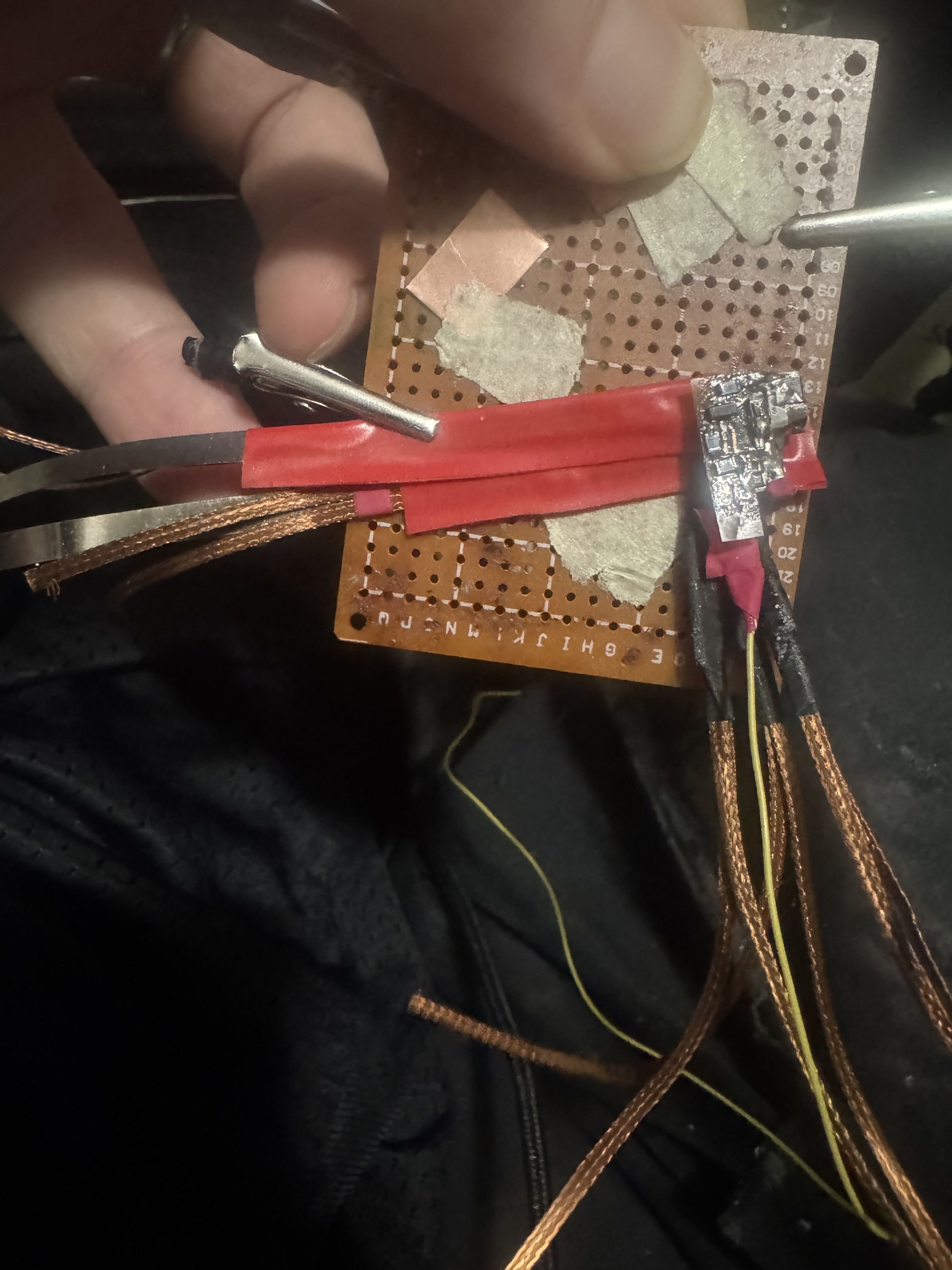
On another note, I noticed that stacking the 0.1mm x 4mm x 100mm nickel strip plus braided solder wick to reduce resistance and increase conductivity made the lines a bit thicker than I'd like, especially after adding tape. So to resolve this I decided to roll with 0.2mm x 6mm x 100 mm hand cut out strips of pure copper plate. I was not aware of this option before but I was able to find copper in .2mm thickness in a roll on amazon that I can use for this. With this thicker size and the much lower resistance of copper I should be able to run 30a through it with less than 1w of waste heat which is great. And this will still give me a way thinner result than what I used on this first one while lending lower resistance by getting rid of nickel strip entirely for the high amp stuff (aside from the shunt resistor nickel strip which I still plan to keep). 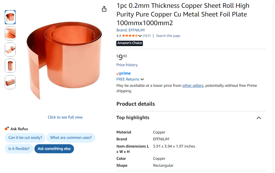
Drop a Comment: Comments: ---------------------------------------------------------------------------- Blog Post #107, submitted 12/24/25 Well I tested printing directly onto Pyralux copper and it was a massive failure. Not even one spec of ink stayed on it and the print came out a inch off the location of the copper. Chatgpt said this is because copper can't hold a electro static charge long enough to take ink onto itself or w/e. Ah well I can fall back to the method I already used successfully. On that note, I realized printing my blue circuit is bad since a black and white printer won't print as densely and darkly a blue thing as it would a black thing so I have to make my circuit black before printing it. Also I should set my dpi to 600 dpi instead of 1200dpi which will create denser thicker prints for better transfer. Also I should select label paper instead of heavy paper which will work better. Also using Lumicolor Straedler pen is not good as it can be undercut easily supposedly. Better to use oil based marker instead. So I ordered that in 0.3mm tip. These are all improvements chatgpt suggested and I plan to use when printing onto the pcb transfer paper and hand touching those up if needed. I'm getting ready to make a bunch of flex pcbs for finishing this motor controller. I already started doing it. Another disaster happened to me as well: my highside circuit I just soldered the solder wick wire onto, when I was analyzing it closely on the front I noticed that excess solder from the drain side of it oozed and dripped toward the front side of it and attached to the gate pin! I heated up that attachment point from the front side and my capacitor and resistor from gate to source both came off from the heat! Anyways I heated it up to remove that short circuit and used a xacto knife to wedge between the gate pin and back of mosfet's drain pad which had a solder bridge. I got through the bridge successfully but now have to redo the gate to source resistor and capacitor. Ugh! Two steps forward one step back. Then while inspecting and cleaning everything I moved the control circuitry a bit too much and it broke off for the 3rd time! So that has to be done again. This time I'm using flat flex for it. I've had it with the non flat flex variant breaking. The flat flex is way more solid mechanically. So that's a redo needed. Ugh. Then to top it all off, the solder wick braids recent idea I had to electrically isolate their run near to the mosfet so that they aren't live for very long - which had to do with wanting to eliminate any short circuit risks in their longer run as well as remove any potential for antenna affects - yeah... well after cutting them all in half to do this transition idea, as I was doing it, I realized the surface area where the hand-off takes place between one section of solder wick braid and onto the next seems very small to me (2mm wide by 6mm long) and it seemed to me that the passage of heat across this tiny bridge of thermal tape might be severely compromised and would depend on how tight I made the squeeze of the two pieces of solder wick braid together as well. And I'm not sure I can clamp it tight enough with just tape wrapping it firmly. And if it gets quite hot I'm concerned electrical tape will get gooey and come loose over time and not hold it well. I'm not sure how tight kapton can wrap things I've never used it before so I'm inexperienced with using it and trusting it is hard without experience working with it. This all cumulatively gave me enough doubt that I said heck with it, I'm going to revert to the former plan to just run it live over to the water cooled pipe 3-4" away and use the thermal tape at that junction point where it wraps the pipe. This ensures alot of metal volume is directly tied to the mosfet which means more heat sinking directly with little risk of trapping heat near mosfet - which could happen if my thermal tape junction of copper braid to copper braid were to fail for example by being pulled apart by accident for any reason. Too much risk there IMO. And the risk of a short on account of live wiring it for 3-4" with the live wire sheathed in window screen to emit heat freely but not touch anything I feel is low enough risk IMO. So whatever route I choose has tradeoffs and I feel reverting to my former plan is more robust and foolproof thermally with some minor electrical risks that are mitigated by fuses and careful execution in general. So yeah I had to solder the cut pieces of solder wick braid back together again which was another pain. Note: the next time I solder the heatsink braids onto the drain I plan to use less solder paste so it doesn't ooze and drop forward onto the front circuitry on the front face of the mosfet by accident. I also plan to insulate the front side's circuitry beforehand so even if solder did ooze that way the insulation barrier would prevent short circuits and make the oozing no big deal in theory. So yeah it was a tough session but I learned alot from the mistakes etc. Drop a Comment: Comments: ---------------------------------------------------------------------------- Blog Post #106, submitted 12/23/25 So it hit me that having these braided solder wick wires live all the way to the water cooled pipe distal attachment point is not necessary. And could cause some EMI or noise related issues that is avoidable if I do the following: I can simply cut them off 1/2" from the mosfet, stick thermal tape on one face of the cut off stubs, then stick the rest of the braided solder wick wire run against that thermal tape, then wrap this joint tightly with electrical tape. Finally we then electrically insulate the braided solder wick that is live but leave the braided solder wick section that is now no longer live completely exposed on the duration of its 3"-4" long run from near the mosfet to the water cooled pipe. This way we have electrical isolation near to the mosfet, no antenna effect, no need for window screens now, and no live wires hanging out that aren't properly insulated. Thermal conductivity is reduced negligibly with this solution. This should be trivial to implement as well. It's the perfect solution here and very fast to implement. It may even be slightly less work than dealing with window screens would have been. Drop a Comment: Comments: ---------------------------------------------------------------------------- Blog Post #105, submitted 12/22/25 I used my jumbo Weller W100P soldering iron to attach my 6 solder wick braids to the back of the highside mosfet today and it attached instantly without a hitch. I used low temp solder paste liberally between the two on both surfaces then with my left hand smashed then together with the tip of a xacto knife pressed down onto the solder wick braids from the back. Then I brought in the giant soldering iron and it liquefied the solder in about 1 second despite all that metal involved because it holds such a massive amount of thermal energy that it can deliver on demand very quickly. Such a easier time than trying to do bigger soldering jobs with a micro tip regular soldering iron which often ends with cold joints and stuff. Also since the liquefication went so fast nothing nearby desoldered which is a huge plus. 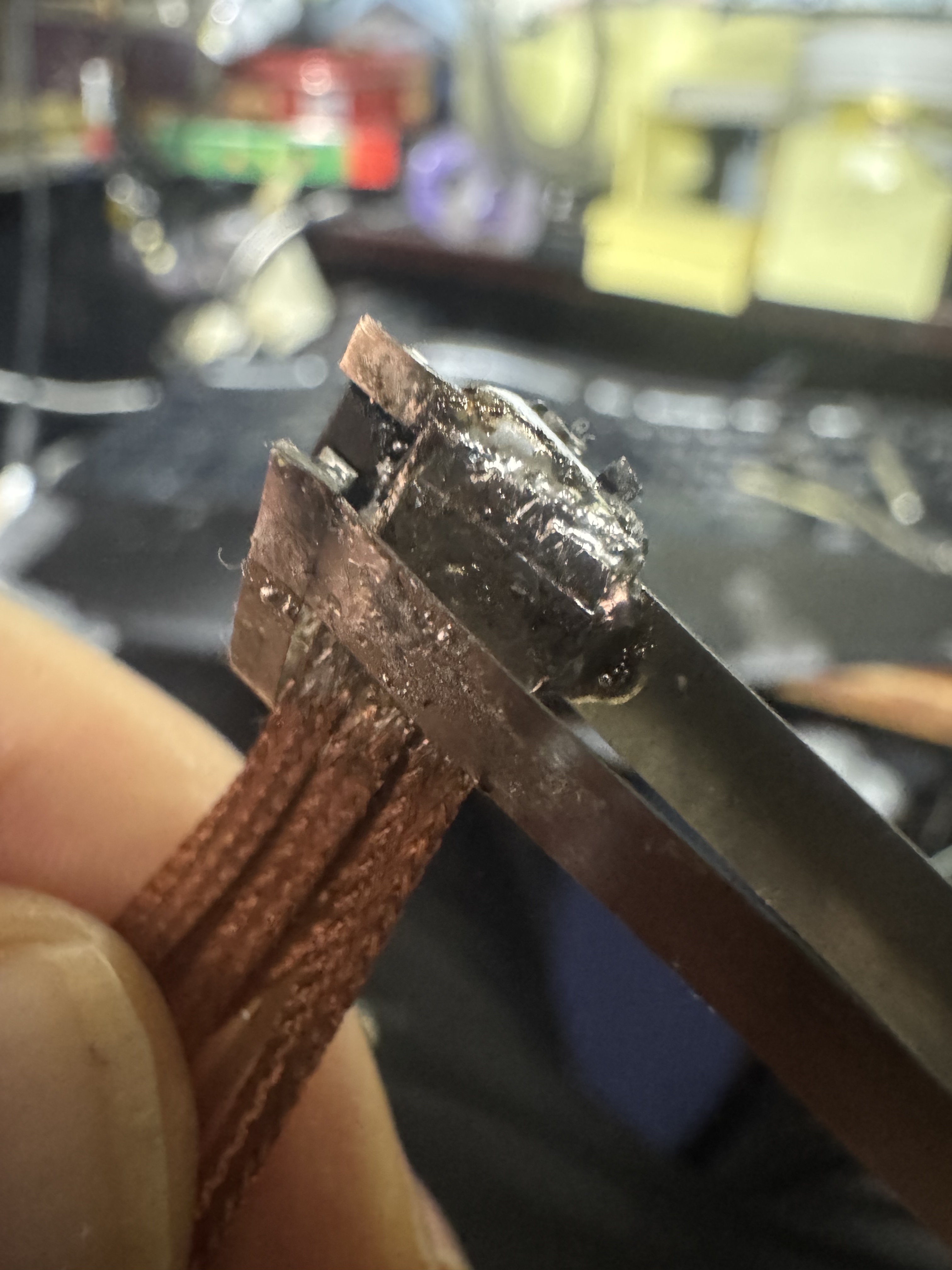
Next up: add the solder wick braids to the underside of nickel strips to lessen resistance there and then insulate this highside switch assembly and install against motor and start finalizing wire run plans. Then I can rinse repeat this for the lowside switch assembly. Then I'll have one of the 3 half bridges done for the motor controller. Drop a Comment: Comments: ---------------------------------------------------------------------------- Blog Post #104, submitted 12/21/25 I did some research of some loose ends today on chatgpt and discovered that my .1mm x 4mm x 60mm sections of nickel strip on my bldc motor controllers that run from the battery to the motor controller mosfets and from the mosfets out to the motor are too high in resistance and at 30a they would within a few seconds get so hot that they would desolder my low temperature solder paste. So to solve this I will be placing two side by side solder wick braids hugging the underside of the nickel strips which will lower resistance so much that temperature will stop being an issue. They will be a combined .1mm x 4mm x 60mm. Then on future mosfets for this portion I will just use the solder wick braids for this section and not use nickel strips at all because they add too much resistance under this high of amp flow. The 2430 BLDC motors are rated to 25a continuous so my conduit has to also handle that easily without overheating. Another really cool discovery I made today was on the topic of measuring current. I'd been putting this off till now but finally got around to deep diving it with chatgpt and discovered something shocking. So basically it was saying to use a shunt resistor inline with the ground side running from the motor controller to the battery. All the current of the motor controller (30a on the high end) will pass through this resistor as its only path. The special thing about a shunt resistor is that its resistance is so low that it doesn't affect voltage or amps a whole lot. I asked chatgpt if I can use nickel strips as my shunt resistor since a smd shunt resistor it said would overheat fast at 30a. It said yes! So I'll be using a .1mm x 4mm x 30mm section of nickel strip as part of my wire run going from the motor controller back to the battery on the ground side. This will act as my homemade shunt resistor. Now the way the arduino will read the amount of current is the analogue input pin will feed into the upstream side (closest to motor controller) of the shunt resistor section of nickel strip and the arduino ground will attach to the downstream side of this nickel strip shunt resistor. It will measure the tiny amount of voltage drop that occurs on account of the shunt resistor's resistance. What is really cool is that the voltage drop changes at this resistance and amp level are read granularly enough by the Arduino analogue input pins that I don't even need to amplify them to read them in meaningfully. Some things like strain gauges provide such tiny resistance changes that you have to use a OP AMP amplifier to be able to read the changes in with your analogue input pin of your arduino to detect them meaningfully but in this case, the resistance changes are large enough and the analogue input pins are granular enough to be able to read them in without any amplification. This means reading in the current for my motor controllers requires ZERO components! It's literally just nickel strip which I already had for the battery tab making and some jumper wire or w/e to take in the readings and that's it! No parts to buy. I had bought some hall effect based current sensor kits and they are not needed at all. I wasted my money on them in the past because I did not know about this shunt resistor option at all at the time. Had I known I would have never bought hall effect based sensor kits - a waste of money. Not to mention they were relatively huge whereas this takes up like practically zero space to measure a shunt resistor section of conduit between the battery and motor controller. So it's awesome news! Note: the current sensing is meant to tell my control system anytime a new unexpected load has hit the motor so it can slow down the flow rate of electric to the motor to prevent burning out something for example or it can also detect any kind of snags or w/e anything getting stuck. It can also help monitor amp flow for the sake of holding the motor in place with stall current kept low enough to prevent overheating etc. It can also act as collision detection if trying to monitor its interactions with its environment and know if something has hit something - which is insanely useful for situational awareness. So it's extremely useful and basically not even optional frankly. To now know that adding this feature is free and super easy to implement and will take up practically ZERO extra space is very exciting to me. Note: my diy shunt resistor (.1mm x 4mm x 30mm section of nickel strip) will have a .005 ohm resistance which is pretty much perfect for my use case it seems (unproven but chatgpt sounds sure of it). It will enable me to monitor the range of 5a to 30a and detect a change in amperage with like 1a granularity. Drop a Comment: Comments: ---------------------------------------------------------------------------- Blog Post #103, submitted 12/19/25 I have two great breakthroughs to announce. First, it suddenly occurred to me that I don't have to print onto PCB transfer paper and then transfer that over to the copper clad Pyralux flat flex PCB but instead I can simply tape the copper clad Pyralux flat flex PCB directly onto my envelope and feed that through my laser printer directly. See, I previously ruled this out when originally researching this stuff because I was planning to use FR-4 PCB which is not flexible nor flat enough to feed through a printer directly. However, now that I am using flat and flexible blank PCB there's no reason not to feed it straight into my laser printer that I'm aware of. Now I haven't tested this but if it works it's a game changer. Will make DIY PCBs that much faster and more streamlined to make! Next, on the subject of attaching the 6 solder wick braids to the mosfets, I was struggling going through the various methods whereby I can tightly clamp it to the mosfet drain and add electrical isolation barrier to the connection point. It's very tight spacing and has to be a very tiny clamping mechanism and the clamp from most directions would have things getting in the way of any clamp design I visualized. It was a nightmare problem IMO. However, my solution I came up with today is game changing: I will simply solder the braids directly to the mosfet drain! This will maximize conductivity off the drain into the braids due to the metal on metal direct connection and eliminate all need for any kind of clamping at all there. Unfortunately, this will make these braids live electrically, but it occurred to me that this is not a big deal. I will simply wrap them in fiberglass window screen to allow them to have great airflow and breath-ability for emissivity of the heat they will be wicking off the mosfet drain and the fiberglass window screen will also act as a physical barrier to them contacting other live metal parts. Window screen is also non-conductive and has good abrasion resistance IMO. I don't anticipate these short wire braid runs to have much contact with anything as they are going to be making short runs from the motor to the water cooling pipe anyways and the exoskeleton mesh that holds up the rubber skin will create spacing and cushion contact bumping or w/e coming from the outside. All in all I think this is a safe solution for the most part and we'll have fuses anyways to prevent major problems in the low risk event of two neighboring live groups of solder wick braid breaking out of their window screen and contacting eachother thereby shorting the circuit. I just see this as highly unlikely but it's covered by the fuse in any case. That all having been said, the electrical isolation barrier stage we now can place at the location where these solder wick braid ends attach to the copper liquid cooling pipe. There at that attachment point I'll put my electrically isolating thermal tape between the solder wick braid and the pipe and clamp things down by tightly wrapping it in electrical tape at the connection point. This is trivial to achieve compared to doing this at the location of the mosfet drain. So we kicked the electrical isolation and clamping problem further downstream than the mosfet drain connection point in order to make the problem a piece of cake. Note: chatgpt said I should tin the braided copper solder wick to prevent oxidization of it which would potentially lower its emissivity. Not sure I agree on this though but I may do it just to be safe we'll see. I'd use MG Chemicals Liquid Tin to do this which I already have on hand for tinning circuit boards. Drop a Comment: Comments: ---------------------------------------------------------------------------- Blog Post #102, submitted 12/7/25 Ok here's the populated board. I tested it with 5v positive and ground and the LED came on so it is for sure not shorting and has continuity so is most likely all working. The next test will be the full lowside switch with this board acting as the drive of the main mosfet for the switch. And once that is validated we can test the entire half bridge (both high and lowside switches). If that checks out, it's all rinse and repeat to make the full motor controller (which is just 3 total half bridges). 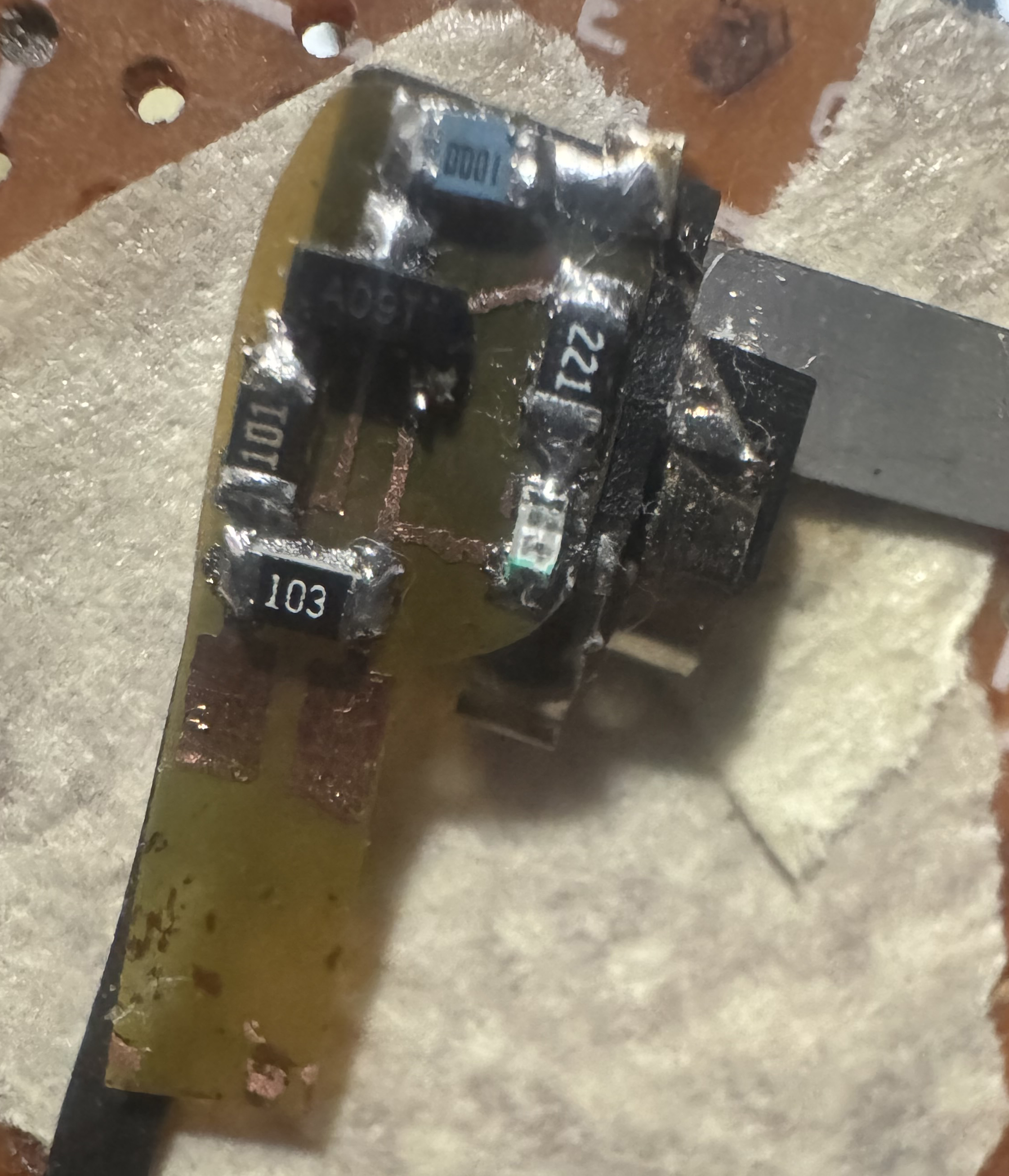
note: I just wanted to hold off on attaching the heatsink for the moment as I validate the first half bridge and once that checks out electronically then I'll get the heatsink attached and go from there. Drop a Comment: Comments: ---------------------------------------------------------------------------- Blog Post #101, submitted 12/6/25 I successfully made a viable flex pcb on my second attempt. I started by printing the circuit onto a mailing envelope using my laser printer. Then I taped a piece of toner transfer paper for pcbs shiny side up directly over where the print on the envelope was. This way I could use just a tiny bit of the expensive toner paper and know the printer would hit that exact spot again when I reload the envelope in the same spot. 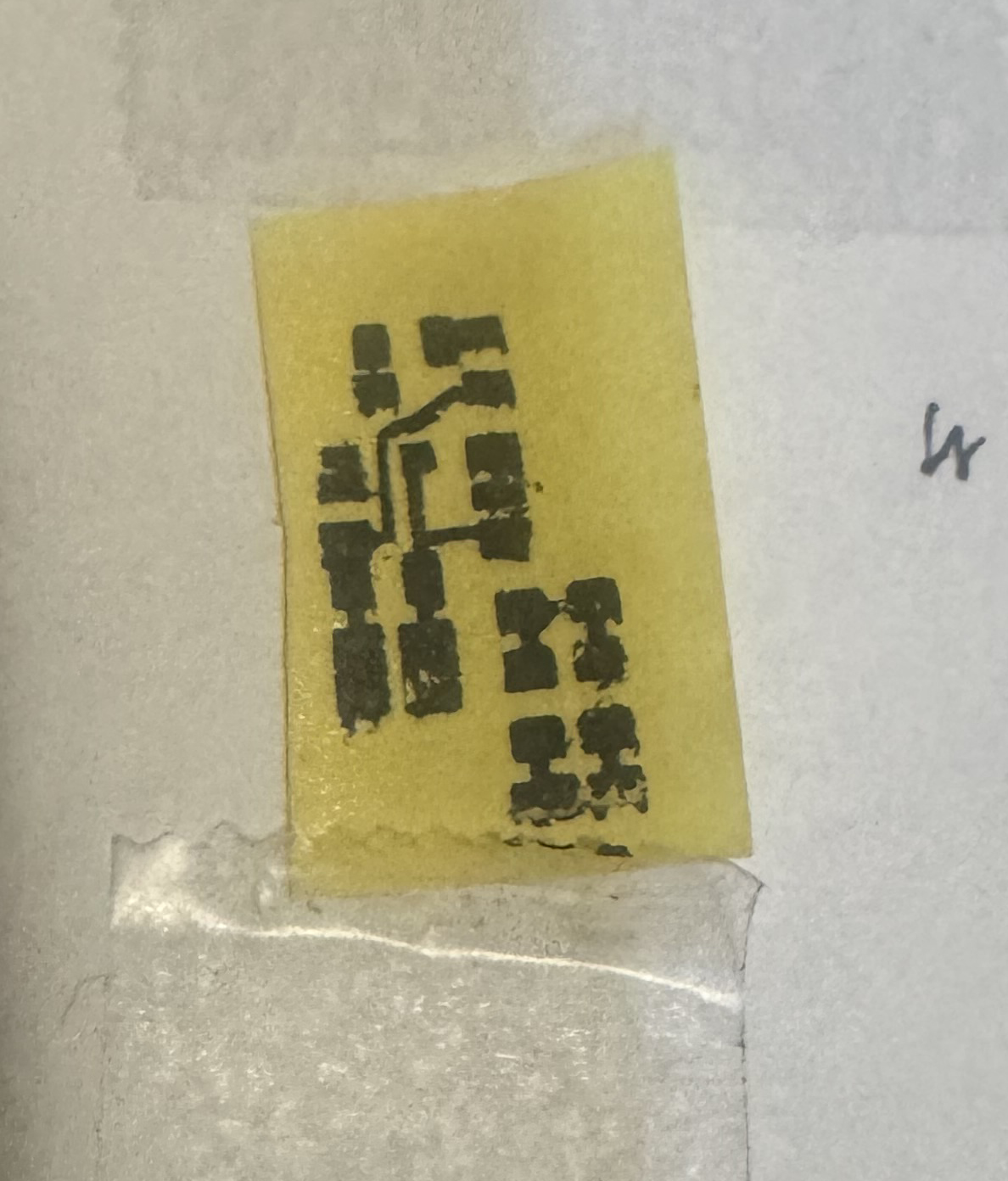
The print landed right on the toner transfer paper according to plan. I then sanded with 400 grit sandpaper the Pyralux flat flex PCB copper blank and wiped it off with a alcohol prep pad. These actions clear any oils and oxidation and give more bite for the toner to cling to the board better. I then taped directly onto this toner transfer paper print the Pyralux flat flex pcb copper blank. No need to even take it off the envelope. Just taped it right over it and fed the whole sandwiched assembly through my laminator a few times envelope and all. 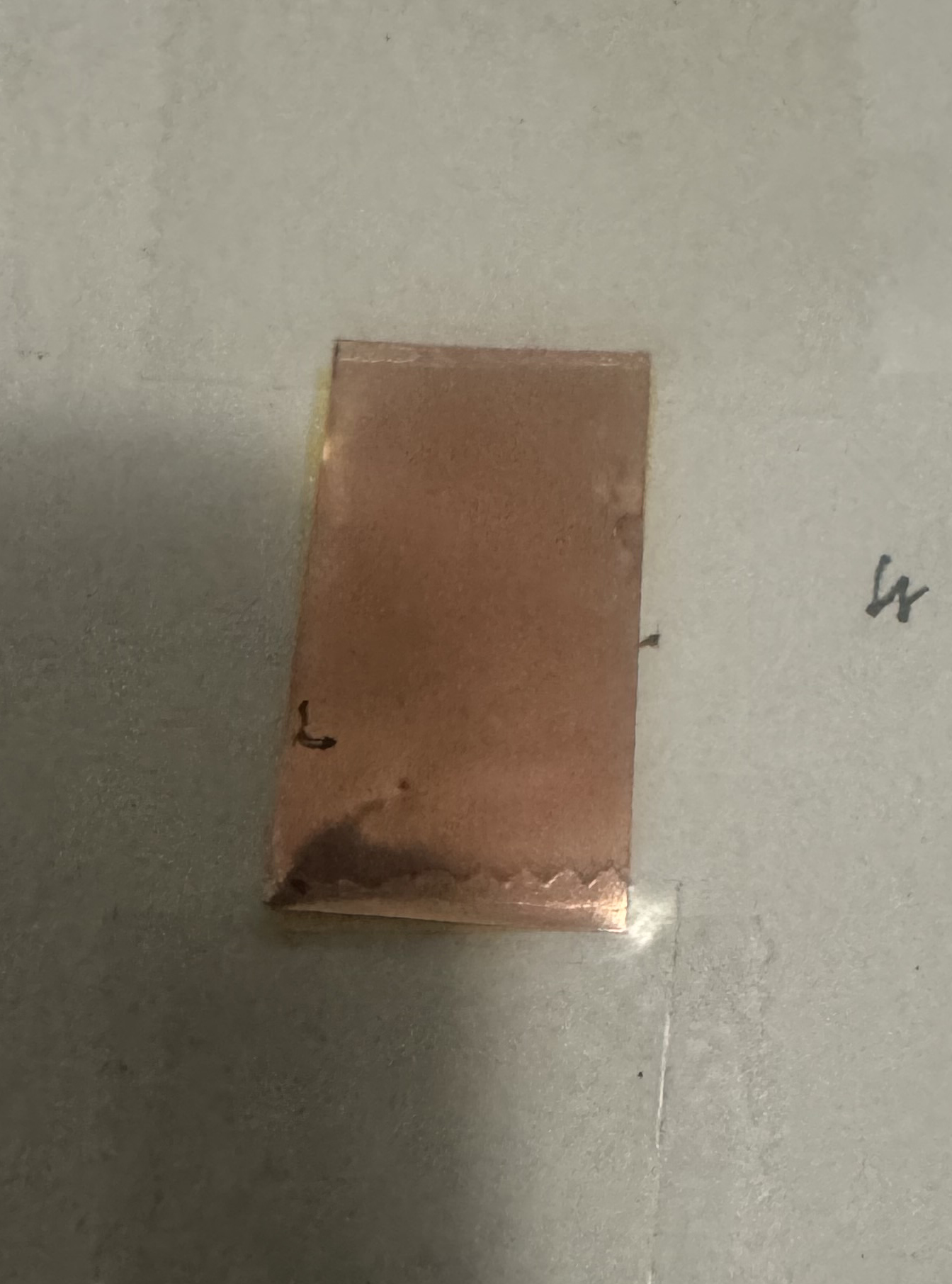
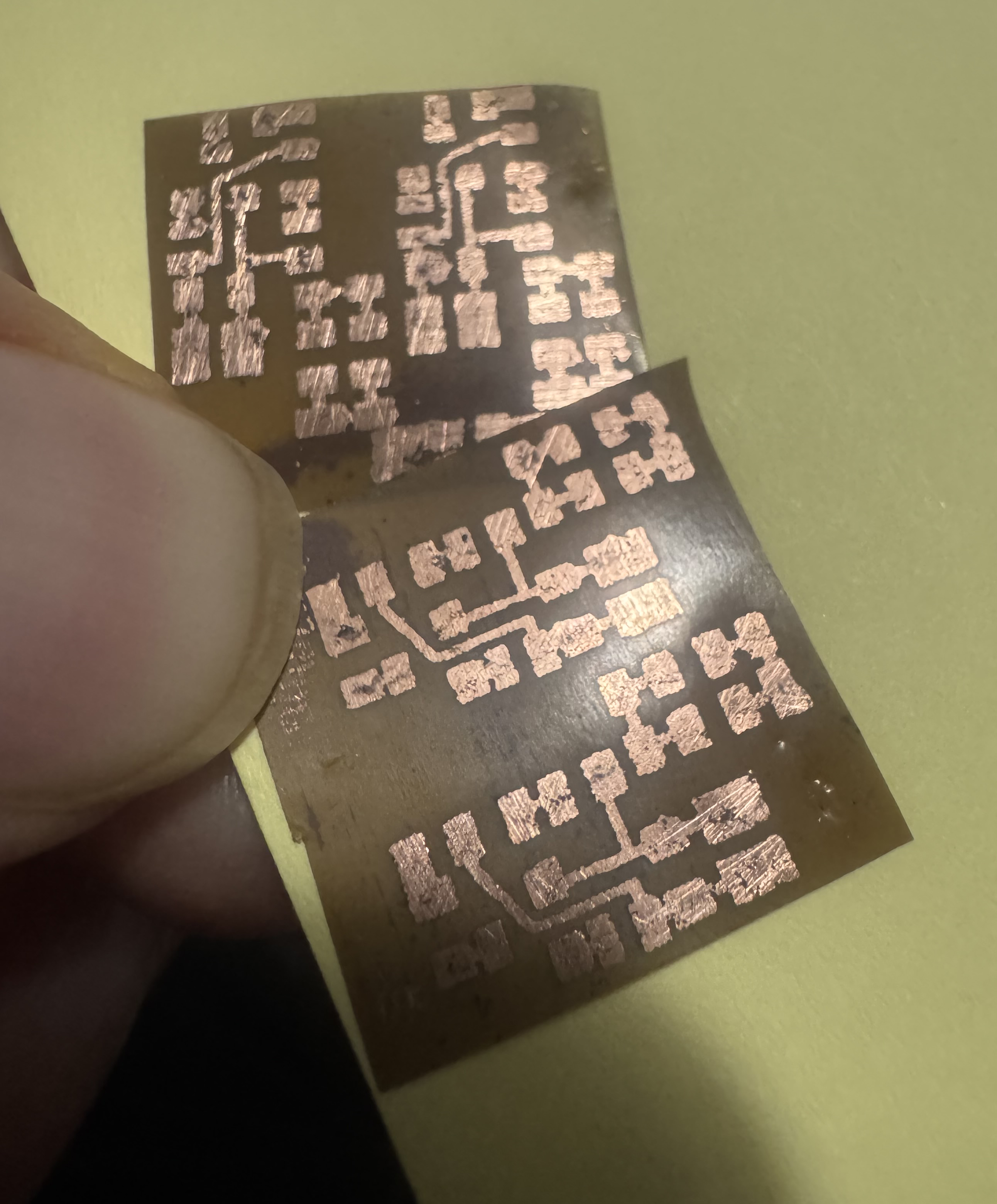
When I peeled back the Pyralux flat flex PCB my laser printer's toner was indeed transferred over to the Pyralux flat flex PCB's copper. I prepared etchant solution mix of 1 part etchant powder to 4 parts water. I just eyed this roughly and think I did not put in enough echant which causes undercutting of the traces under the toner and slower etching. Lesson learned. 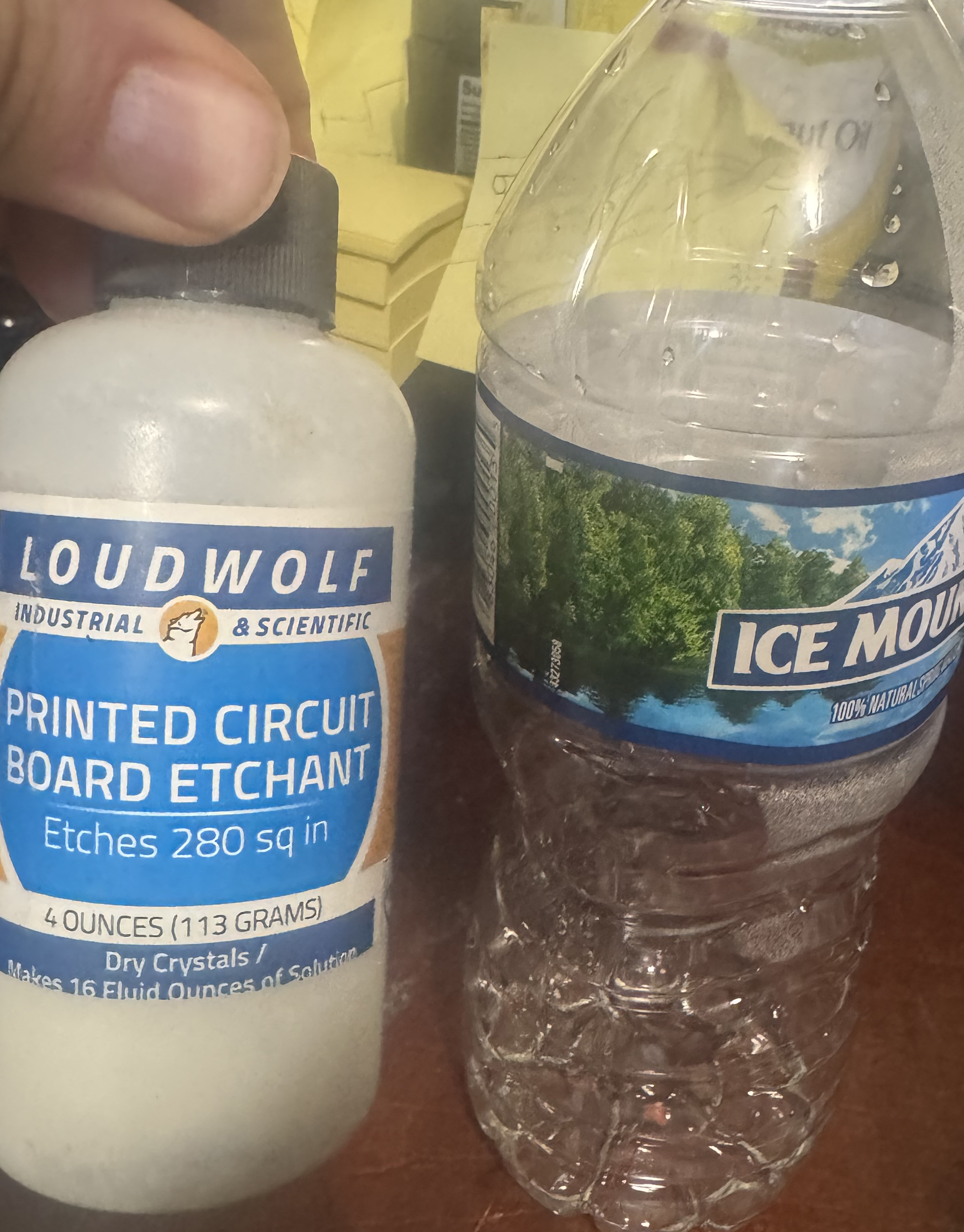
I mixed it in a silicone earplugs container. My aim was a small container to make a smaller batch of the etchant to cut down on etchant used since I'm only doing a very small PCB. 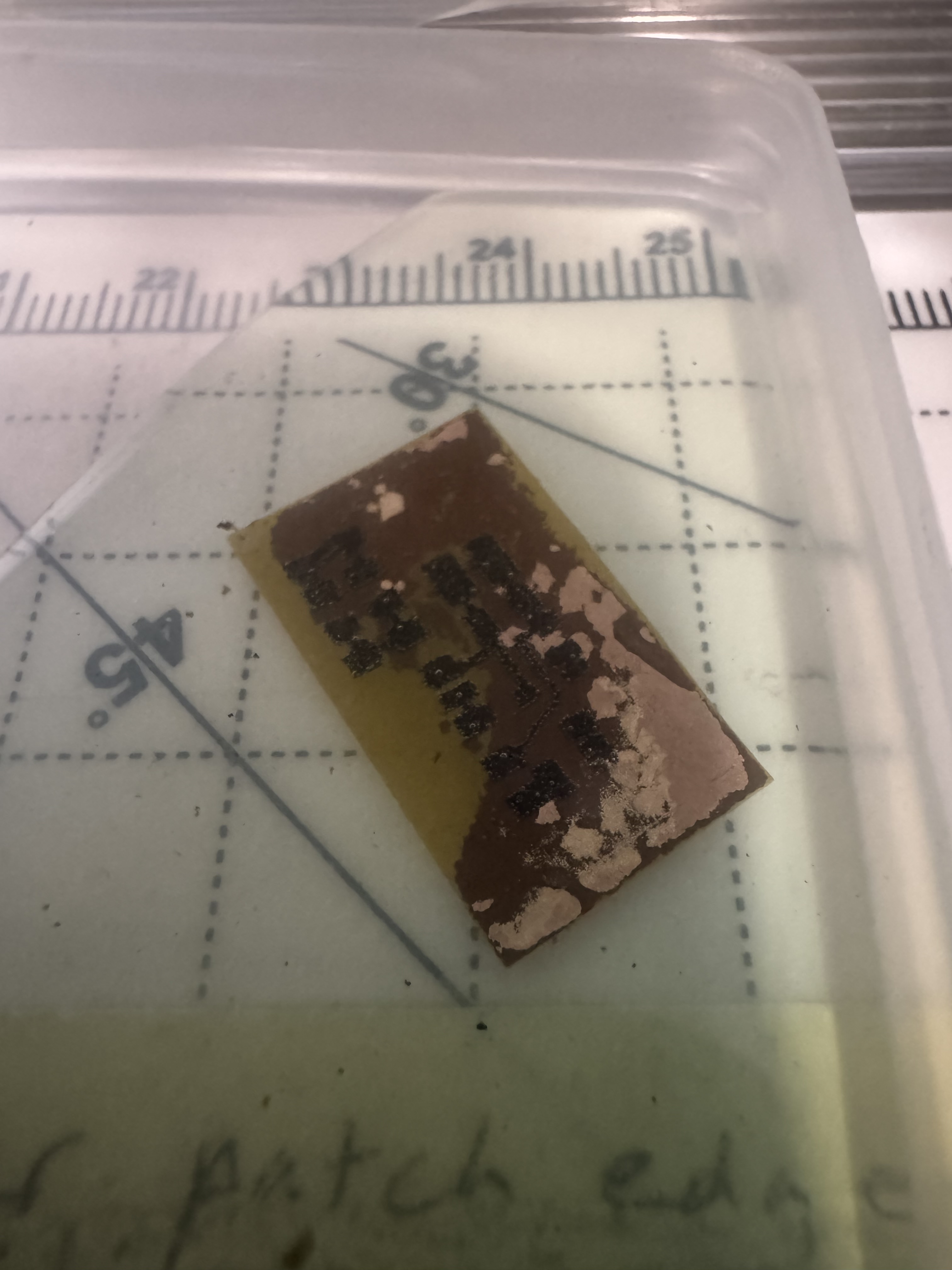
The first board I left etching for a couple hours unattended which was a mistake. It was unusable. A ton of the copper under the toner was missing which is called undercutting. I left it etching for too long which causes this. The second board came out pretty good. But I used the exhuasted etchant from the first board which was already too diluted and so the results were meh but good enough to use IMO. 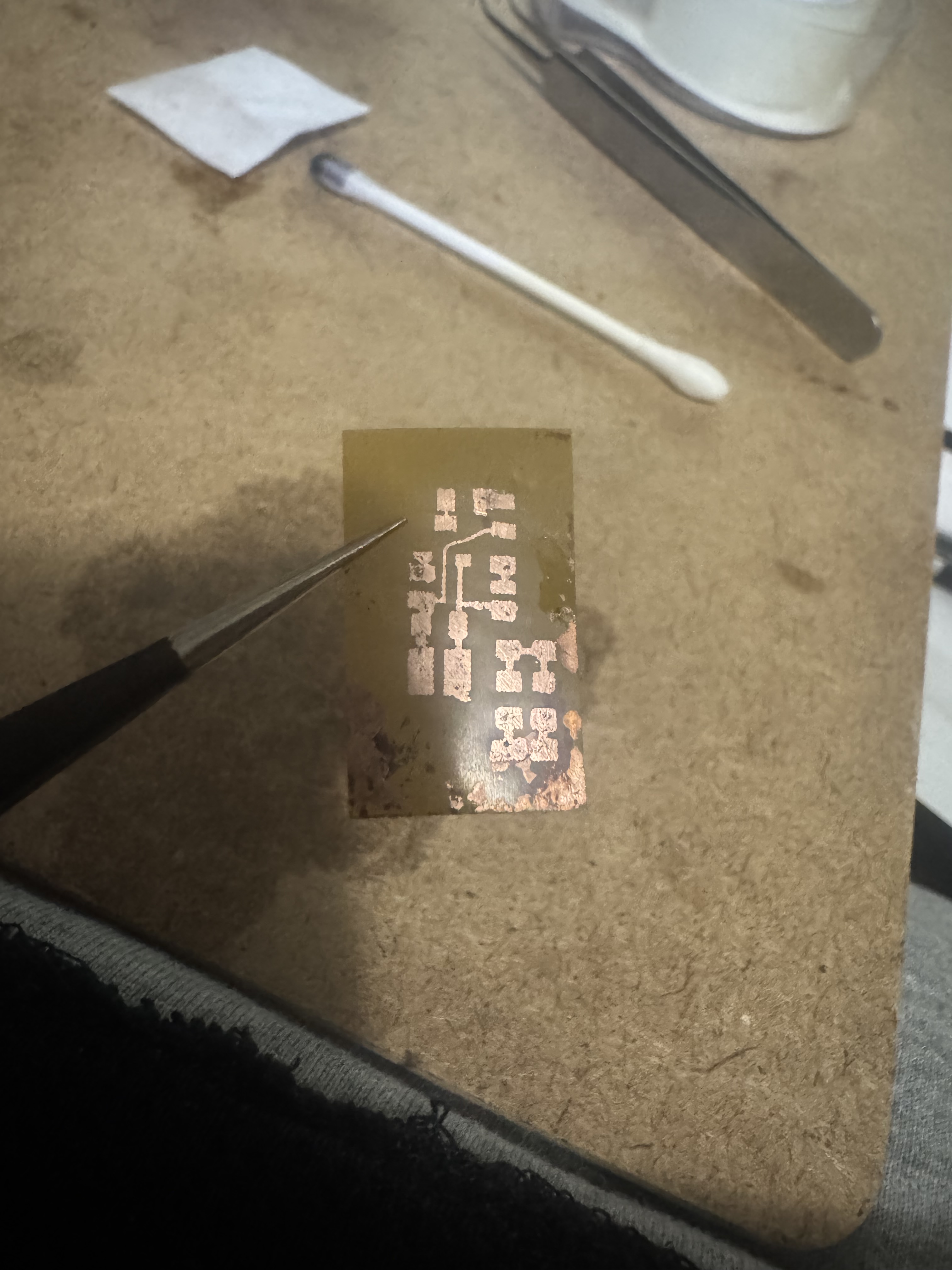
Note: the prints going onto the toner transfer paper are not very high quality and sometimes has missing spots so AFTER transferring it to the copper I used a Straedler permanent lumoocolor super fine tipped pen and magnification to carefully color in any missing spots where the laser printer failed to deposit enough toner or the toner failed to transfer perfectly enough. I used stippling method with the pen - just dotting over and over rather than drawing to get max precision for cleanup of the tiny pads and traces on the copper. Note: I never had to use water to remove the toner paper from the pcb. Just laminating it a few times through my laminator was enough for the transfer to take place and I was able to cleanly peel it away. This meant the toner transfer paper could remain taped to the envelope and be reused indefinitely. I reused it a few times successfully as I dialed in the processes. This is very nice. Saves time for sure. Note: I did attempt to not sand nor alcohol treat the Pyralux copper pcb blank and toner transfer onto virgin copper blank but it did not adhere well enough so I reverted to the recommended sanding and wiping after all. Was worth a shot to save steps but did not work out. Note: I used heavy paper setting in photoshop during the print dialogue settings because the normal print settings were kind of messing up for me. I also think this printer is not very well suited for this. My other laser printer has a "best" quality option and did very nice prints but this one is a cheapo I'm using and only has "fast" quality but worked well enough nonetheless for the most part. Note: I assumed I could use this etchant over and over and over but chatgpt said it gets exhausted and loses efficacy and should only be used once. Some acids people made online you could use over and over but I guess not this type not sure. Note: the acid etchant I'm using says it only releases oxygen so the fumes I guess are not bad like some other kinds of etchant - correct me if I'm wrong on that though. Note: I used a q-tip and lacquer thinner to remove the toner after the etching was done. Note: use black, NOT blue for circuit in photoshop so that it will print more dark (otherwise printer prints the black spotty to lighten it and this means less toner and less good results of traces ouch!) Note: in photoshop during printer settings dialogue, select paper type: labels or heavy (labels preferred); transparency is also a good option? Note: in photoshop during printer settings dialogue, use 600dpi instead of 1200 FastRes (600 dpi gives you thicker, more transferable toner.) Drop a Comment: Comments: Older Posts |
|
|||
|
||||
| *REGISTERED NAMES AND TRADEMARKS ARE THE PROPERTY OF THEIR RESPECTIVE OWNERS. |
|
Page Hits: 53424. |